Structural Analysis
6th Edition
ISBN: 9781337630931
Author: KASSIMALI, Aslam.
Publisher: Cengage,
expand_more
expand_more
format_list_bulleted
Question
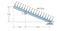
Draw the FBD
All distributed loads should be simplified to their equivalent loads
Draw the FBD where the system is the bar

Transcribed Image Text:The diagram depicts a beam inclined at an angle, subject to a uniformly distributed load. Here's a detailed description:
### Diagram Description
1. **Inclined Beam:**
- The beam is positioned on an incline, sloping downwards from left to right.
- It is pinned at two supports, labeled A and B.
2. **Supports:**
- Support A is located 1 meter from the left end of the beam.
- Support B is placed 3 meters from the right end of the beam, making it 4 meters from the left end.
3. **Beam Dimensions:**
- The total length of the beam is 4 meters.
- There is a vertical separation of 3 meters between the top and bottom of the beam due to the incline.
4. **Distributed Load:**
- The beam is subject to a uniformly distributed load of 800 N/m.
- This load acts vertically downwards along the length of the beam.
5. **Load Distribution:**
- The arrows on the diagram represent the direction and uniform distribution of the load across the beam.
This setup is often used to analyze static equilibrium in mechanical systems, where the reactions at the supports and the internal forces within the beam are determined based on the applied loads.
Expert Solution
This question has been solved!
Explore an expertly crafted, step-by-step solution for a thorough understanding of key concepts.
Step by stepSolved in 2 steps with 2 images

Knowledge Booster
Learn more about
Need a deep-dive on the concept behind this application? Look no further. Learn more about this topic, civil-engineering and related others by exploring similar questions and additional content below.Similar questions
- Base on the gravity load path of the one-way system shown above, explain what is occurring at each of the labeled points.arrow_forwardMake correction to this exercice and explain in sentence or two why I made the mistake.arrow_forwardWhere is the location of the resultant force for the distributed load below? 400 N/m -3 m AQ O2m to the right of A O 1m to the left of B O 1m to the Left of A O At A 2m to the left of B 3 m Barrow_forward
- The bridge is pinned at A and has a roller at G. A downward load of 12.5 lb is applied at point C, and a downward load of 25 lb is applied at E. The support reactions at the pin and roller are shown on the image. Find the stress in members making up the bridge using either the method of joints or method of sections.arrow_forwardAsap plzarrow_forwardA beam and its loading is shown where F1= 1000 N/m. F1 1600 N/m A B 6 m Determine the magnitude and location of the resultant of the distributed load. (You must provide an answer before moving to the next part.) The magnitude of the resultant of the distributed load is The location of the resultant of the distributed load is m. (Click to select)arrow_forward
- Draw the shear diagram for the beam. Click on "add discontinuity" to add discontinuity lines. Then click on "add segment" button to add functions between the lines. +O No elements selected 1 kip/ft V (kip) 5 4 3 2 1 0 in bo & Ń -2 0 5 15 ft 10 2 kip/ft 15 z (ft)arrow_forwardDraw the shear diagrams for the following two figures:arrow_forwardEstimate the loads applied on the Beam 1, including the load transferred from Slabs 1 and 2 (self-weight of slabs), the self-weight of Beam 1 and the water tank load. Note that the water tank load may be idealised as a point load. Please also note that there are also other types of loads, which should be considered for practical design, but for simplicity they are not considered here.arrow_forward
arrow_back_ios
arrow_forward_ios
Recommended textbooks for you

 Structural Analysis (10th Edition)Civil EngineeringISBN:9780134610672Author:Russell C. HibbelerPublisher:PEARSON
 Principles of Foundation Engineering (MindTap Cou...Civil EngineeringISBN:9781337705028Author:Braja M. Das, Nagaratnam SivakuganPublisher:Cengage Learning
 Fundamentals of Structural AnalysisCivil EngineeringISBN:9780073398006Author:Kenneth M. Leet Emeritus, Chia-Ming Uang, Joel LanningPublisher:McGraw-Hill Education
 Traffic and Highway EngineeringCivil EngineeringISBN:9781305156241Author:Garber, Nicholas J.Publisher:Cengage Learning


Structural Analysis (10th Edition)
Civil Engineering
ISBN:9780134610672
Author:Russell C. Hibbeler
Publisher:PEARSON

Principles of Foundation Engineering (MindTap Cou...
Civil Engineering
ISBN:9781337705028
Author:Braja M. Das, Nagaratnam Sivakugan
Publisher:Cengage Learning

Fundamentals of Structural Analysis
Civil Engineering
ISBN:9780073398006
Author:Kenneth M. Leet Emeritus, Chia-Ming Uang, Joel Lanning
Publisher:McGraw-Hill Education


Traffic and Highway Engineering
Civil Engineering
ISBN:9781305156241
Author:Garber, Nicholas J.
Publisher:Cengage Learning