
Steel Design (Activate Learning with these NEW titles from Engineering!)
6th Edition
ISBN: 9781337094740
Author: Segui, William T.
Publisher: Cengage Learning
expand_more
expand_more
format_list_bulleted
Related questions
Question
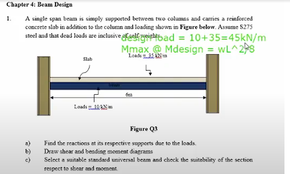

Transcribed Image Text:Chapter 4: Beam Design
1.
A single span beam is simply supported between two columns and carries a reinforced
concrete slab in addition to the column and loading shown in Figure below. Assume S275
steel and that dead loads are inclusive fself weightad = 10+35=45kN/m
Mmax @ Mdesign = wL^2
Loads 35 kN m
Slab
Loads .10 KN m
Figure Q3
a)
b)
Find the reactions at its respective supports due to the loads.
Draw shear and bending moment diagrams
c)
Select a suitable standard universal beam and check the suitability of the section
respect to shear and moment.
Expert Solution
This question has been solved!
Explore an expertly crafted, step-by-step solution for a thorough understanding of key concepts.

Step by stepSolved in 6 steps with 2 images

Knowledge Booster


Learn more about
Need a deep-dive on the concept behind this application? Look no further. Learn more about this topic, civil-engineering and related others by exploring similar questions and additional content below.Similar questions
- A column in a building is subjected to the following load effects: 9 kips compression from dead load 5 kips compression from roof live load 6 kips compression from snow 7 kips compression from 3 inches of rain accumulated on the roof 8 kips compression from wind a. If lead and resistance factor design is used, determine the factored load (required strength) to be used in the design of the column. Which AISC load combination controls? b. What is the required design strength of the Column? c. What is the required nominal strength of the column for a resistance factor of 0.90? d. If allowable strength design is used, determine the required load capacity (required strength) to be used in the design of the column. Which AISC load combination controls? e. What is the required nominal strength of the column for a safety factor of 1.67?arrow_forwardA beam must be designed to the following specifications: Span length = 35 ft Beam spacing = 10 ft 2-in. deck with 3 in. of lightweight concrete fill (wc=115 pcf) for a total depth of t=5 in. Total weight of deck and slab = 51 psf Construction load = 20 psf Partition load = 20 psf Miscellaneous dead load = 10 psf Live load = 80 psf Fy=50 ksi, fc=4 ksi Assume continuous lateral support and use LRFD. a. Design a noncomposite beam. Compute the total deflection (there is no limit to be checked). b. Design a composite beam and specify the size and number of stud anchors required. Assume one stud at each beam location. Compute the maximum total deflection as follows: 1. Use the transformed section. 2. Use the lower-bound moment of inertia.arrow_forwardDetermine the smallest value of yield stress Fy, for which a W-, M-, or S-shape from Part 1 of the Manual will become slender. To which shapes does this value apply? What conclusion can you draw from your answer?arrow_forward
- Compute the nominal shear strength of an M107.5 of A572 Grad 65 steel.arrow_forwardUse the composite beam tables and select a W-shape and stud anchors for the following conditions: Span length = 18 6 Beam spacing = 9 ft Total slab thickness = 51 2 in. (the slab and deck combination weighs 57 psf). Lightweight concrete with a unit weight of 115 pcf is used Construction load = 20 psf Partition load = 20 psf Live load = 225 psf Fy=50 ksi and fc=4 ksi A cross section of the formed steel deck is shown in Figure P9.8-9. The maximum live-load deflection cannot exceed L/360 (use a lower-bound moment of inertia). a. Use LRFD. b. User ASD.arrow_forwardIf the beam in Problem 5.5-9 i5 braced at A, B, and C, compute for the unbr Cb aced length AC (same as Cb for unbraced length CB). Do not include the beam weight in the loading. a. Use the unfactored service loads. b. Use factored loads.arrow_forward
- Compute the nominal shear strength of an M1211.8 of A572 Grade 65 steel.arrow_forwardA plate girder must be designed for the conditions shown in Figure P10.7-4. The given loads are factored, and the uniformly distributed load includes a conservative estimate of the girder weight. Lateral support is provided at the ands and at the load points. Use LRFD for that following: a. Select the, flange and web dimensions so that intermediate stiffeners will he required. Use Fy=50 ksi and a total depth of 50 inches. Bearing stiffeners will be used at the ends and at the load points, but do not proportion them. b. Determine the locations of the intermediate stiffeners, but do not proportion them.arrow_forwardusing Figure 5-27, what is the advantage of the suspended type magnet over the other two types of magnets?arrow_forward
- A tensile test was performed on a metal specimen having a circular cross section with a diameter 0. 510 inch. For each increment of load applied, the strain was directly determined by means of a strain gage attached to the specimen. The results are, shown in Table: 1.5.1. a. Prepare a table of stress and strain. b. Plot these data to obtain a stress-strain curve. Do not connect the data points; draw a best-fit straight line through them. c. Determine the modulus of elasticity as the slope of the best-fit line.arrow_forwardThe data in Table 1.5.3 were obtained from a tensile test of a metal specimen with a rectangular cross section of 0.2011in.2 in area and a gage length (the length over which the elongation is measured) of 2.000 inches. The specimen was not loaded to failure. a. Generate a table of stress and strain values. b. Plot these values and draw a best-fit line to obtain a stress-strain curve. c. Determine the modulus of elasticity from the slope of the linear portion of the curve. d. Estimate the value of the proportional limit. e. Use the 0.2 offset method to determine the yield stress.arrow_forward
arrow_back_ios
arrow_forward_ios
Recommended textbooks for you
- Steel Design (Activate Learning with these NEW ti...Civil EngineeringISBN:9781337094740Author:Segui, William T.Publisher:Cengage Learning
 Materials Science And Engineering PropertiesCivil EngineeringISBN:9781111988609Author:Charles GilmorePublisher:Cengage Learning
 Engineering Fundamentals: An Introduction to Engi...Civil EngineeringISBN:9781305084766Author:Saeed MoaveniPublisher:Cengage Learning
  Solid Waste EngineeringCivil EngineeringISBN:9781305635203Author:Worrell, William A.Publisher:Cengage Learning,
Steel Design (Activate Learning with these NEW ti...
Civil Engineering
ISBN:9781337094740
Author:Segui, William T.
Publisher:Cengage Learning
Materials Science And Engineering Properties
Civil Engineering
ISBN:9781111988609
Author:Charles Gilmore
Publisher:Cengage Learning
Engineering Fundamentals: An Introduction to Engi...
Civil Engineering
ISBN:9781305084766
Author:Saeed Moaveni
Publisher:Cengage Learning
Solid Waste Engineering
Civil Engineering
ISBN:9781305635203
Author:Worrell, William A.
Publisher:Cengage Learning,