Structural Analysis
6th Edition
ISBN: 9781337630931
Author: KASSIMALI, Aslam.
Publisher: Cengage,
expand_more
expand_more
format_list_bulleted
Concept explainers
Question
thumb_up100%

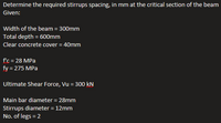
Transcribed Image Text:Determine the required stirrups spacing, in mm at the critical section of the beam
Given:
Width of the beam = 300mm
Total depth = 600mm
Clear concrete cover = 40mm
f'c = 28 MPa
fy = 275 MPa
Ultimate Shear Force, Vu = 300 kN
Main bar diameter = 28mm
Stirrups diameter = 12mm
No. of legs = 2

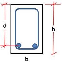
Transcribed Image Text:d
h
b
Expert Solution
This question has been solved!
Explore an expertly crafted, step-by-step solution for a thorough understanding of key concepts.
Step by stepSolved in 2 steps

Knowledge Booster
Learn more about
Need a deep-dive on the concept behind this application? Look no further. Learn more about this topic, civil-engineering and related others by exploring similar questions and additional content below.Similar questions
- Design a bearing plate at the support for a roof beam ISMB 600 @ 1202.71 N/m resting on a concrete pedestate masonry wall 250mm thick for the following data: Reation 200 kN Grade of concrete : M-20 For ISMB 600@ 1202.71 N/m Width of flange, b, = 210mm Thickness of flange, t = 20.8mm Thickness of web, t = 12mm Radius at root, R₁ = 20mmarrow_forward3) Calculate the nominal moment strength and the design ultimate moment of the precast T-beam shown in Figure if the beam span is 30 ft. Given: f=4000 psi, normal-weight concrete fy=60,000 psi Reinforcement area at the tension side: 2 in. 40 in. 4 No. 9 bars 10 in. 2.5 in. 20 in.arrow_forwardA built-up tee-shape beam section consists of 2 steel plates 7/8 in. x 10-in. flange and a 1-in. x 12-in web. The yield stress Fy is 50ksi. Calculate the yield moment in kip-ft. Express your answer in 2 decimal places.arrow_forward
- A rectangular beam has b = 350 mm and d = 460 mm.the concrete compression strength is 30 MPa and the steelyield strength fy = 415 MPa. Calculate the required steelreinforcement area if the steel cover is 70 mm.use NSCP 2010 Md = 230 KN-mML = 160 KN-marrow_forwardPLEASE INCLUDE COMPLETE SOLUTIONarrow_forwardThe deep beam shown below supports a factored load of 1500 kips. Draw a truss model neglecting the effects of stirrups and the dead load of the wall. Check the strength of the nodes and structs and design the tension tie. Use 5 ksi normal-weight concrete and fy = 60 ksi. Consider the overall beam height of 12 ft and the effective depth is approximately 11 ft 32" 6 ft A B 1500 kips C 34 in 21 ft D 28"arrow_forward
- See the image below. A hot-rolled l-beam section has yield strength fy = 300 MPa, ultimate strength fu = 320 MPa. b = 158 mm, t = 10 mm, H = 266 mm, tw = 13 mm. Calculate the nominal shear capacity of this section (in kN, round to whole number). b I H tw Harrow_forwardSITUATION A: The floor system shown has the following applied loads. Super Imposed Dead Load = 2.00 kPa Live Load = 1.90 kPa Slab Thickness = 100.00 mm Weight of Concrete = 24 kN/m3 Self-Weight of the beam = 1.92 kN/m Material Specifications: f’c = 21.00 MPa fy = 345.00 MPa Steel Cover = 50.00 mm What is the maximum positive moment of beam BE, acting on the midspan? in kN-m What is the maximum steel ratio of the section located at the supports? What is the actual steel ratio of the beam section at the supports? What is the ultimate moment capacity of the beam at the supports? in kN-m What is the effective flange width at the midspan? in mm What is the height of the compression block of the section at midspan? in mm What is the ultimate moment capacity of the beam at the midspan? in kN-m What would be the height of the CHB that can be placed on beam BE? Assuming the weight of the blocks is 2.30 kN/m per meter height? in metersarrow_forwardDesign the reinforcement of the section shown. For concrete, fc' = 21 MPa and for steel, fy = 275 MPa. Beam section has a width of 250 mm and a total depth of 500 mm. The steel cover is 70 mm. a. WD = 5 kN/m (including beam weight), WL = 6 kN/m b. WD = 2 kN/m (including beam weight), WL = 1 kN/m c. WD = 15 kN/m (including beam weight), WL = 26 kN/marrow_forward
- A reinforced concrete beam that is 375 mm wide and 500mm deep must resist a service live load moment of 250 kN-m and a service dead load moment of 150 kN-m. Use f'c-21 MPa and fy=415 MPa. The effective concrete cover is 65mm (to the centroid of reinforcements). 1. Determine the area of compression steel reinforcement (If required. Answer O if not) in mm² 2. Determine the minimum number of 25 mm diameter bars to be provided to satisfy the demand ultimate moment 3. Determine the maximum number of 25 mm diameter bars to be provided to have a tension controlled section Answer 1: 2403.21 correct answer: Answer 2: 9.00 Answer 3: 8.00arrow_forwardThe beam section below has 4 #7 bars arranged in one row as shown below. The beam has normal- weight concrete with a compressive strength, f, equal to 4,000 psi, and the yield strength of the reinforcing steel is 60 ksi (Grade 60). 14 in. 3 in. 3 in. 164 #7 bars 21 in. 4 in. 15 in. 5 in. (a) Determine M₁, the nominal moment capacity of the beam. n (b) Consider that the section has four #9 tension bars instead of four #7. In addition, it has four #4 bars in the top flange. The centroid of the top bars is 2.5 in. from the top edge of the beam. Determine M₁, the nominal moment capacity of the beam, taking into account of the compression steel.arrow_forward
arrow_back_ios
arrow_forward_ios
Recommended textbooks for you

 Structural Analysis (10th Edition)Civil EngineeringISBN:9780134610672Author:Russell C. HibbelerPublisher:PEARSON
 Principles of Foundation Engineering (MindTap Cou...Civil EngineeringISBN:9781337705028Author:Braja M. Das, Nagaratnam SivakuganPublisher:Cengage Learning
 Fundamentals of Structural AnalysisCivil EngineeringISBN:9780073398006Author:Kenneth M. Leet Emeritus, Chia-Ming Uang, Joel LanningPublisher:McGraw-Hill Education
 Traffic and Highway EngineeringCivil EngineeringISBN:9781305156241Author:Garber, Nicholas J.Publisher:Cengage Learning


Structural Analysis (10th Edition)
Civil Engineering
ISBN:9780134610672
Author:Russell C. Hibbeler
Publisher:PEARSON

Principles of Foundation Engineering (MindTap Cou...
Civil Engineering
ISBN:9781337705028
Author:Braja M. Das, Nagaratnam Sivakugan
Publisher:Cengage Learning

Fundamentals of Structural Analysis
Civil Engineering
ISBN:9780073398006
Author:Kenneth M. Leet Emeritus, Chia-Ming Uang, Joel Lanning
Publisher:McGraw-Hill Education


Traffic and Highway Engineering
Civil Engineering
ISBN:9781305156241
Author:Garber, Nicholas J.
Publisher:Cengage Learning