Introductory Circuit Analysis (13th Edition)
13th Edition
ISBN: 9780133923605
Author: Robert L. Boylestad
Publisher: PEARSON
expand_more
expand_more
format_list_bulleted
Concept explainers
Question

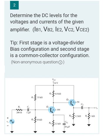
Transcribed Image Text:+= 1
2
Determine the DC levels for the
voltages and currents of the given
amplifier. (IB1, VB2, IE2, VC2, VCE2)
Tip: First stage is a voltage-divider
Bias configuration and second stage
is a common-collector configuration.
(Non-anonymous question Ⓒ)
Vcc
R₁ 33 ΚΩ
B₂=50
1.2 ΚΩ
Rs
200 Ω
Cs
HE
1 μF
R₂
10 ΚΩ
2₁
Rc
14 V
| 6.8 ΚΩ
B₁ = 100
• 2.2 ΚΩ
REI
2₂
CEI
RE2
20 μF
HH
RL
Ovo
1 ΚΩ
Expert Solution
This question has been solved!
Explore an expertly crafted, step-by-step solution for a thorough understanding of key concepts.
Step by stepSolved in 3 steps with 3 images

Knowledge Booster
Learn more about
Need a deep-dive on the concept behind this application? Look no further. Learn more about this topic, electrical-engineering and related others by exploring similar questions and additional content below.Similar questions
- 8) Consider the plot of current is in the emitter of the NPN connected to the input of three different power amplifiers as the output voltage ranges from -Vomax to +Vomax. İN M -Vo,max +V0,max Vo Indicate to which power amplifier class, each curve corresponds: a) Class A is N, Class AB is L, Class B is M d) Class A is M, Class AB is N, Class B is L b) Class A is N, Class AB is M, Class B is Le) Class A is L, Class AB is M, Class B is N c) Class A is M, Class AB is L, Class B is N f) Class A is L, Class AB is N, Class B is Marrow_forwardOf the circuit with the given BJT a) Calculate the values of VE1, VE2, VB1, VB2, IE1, IE2. b) Find the input and output impedance. c) Find the current gain. d) Find the voltage gain. VBE = 0.7 V, VD = 0.7 V, VCC = + 20V, β = 100 , R1 = R2 = 32karrow_forwardPlease provide Handwritten answerarrow_forward
- QUESTION 1: The differential amplifier in Figure P11.4 is biased with a three-transistor current source. The transistor parameters: B = 160 , VBE(on) = 0.68 V, and V= 0. Determine I1, Ic2» Ic4, V CE2, and V CE4• 1 (mA) Format : 8.0238 Ic2 (mA) Ic4 (mA) Format : 8.0929 Format : 0.207 VCE2 (V) Format : 5.98 V CE4 (V) Format : 7.2693 +5 V R = 8.5 k2 Rc = 2 k2 2 k2 ICA Q4 VCE4 Q5 Q3 Q2 VCE2 -5 V Figure P11.4arrow_forwardWhere are shift register circuits used?arrow_forwardQUESTION 5 Given is the principle diagram of a regulated power supply shown below. Reference voltage VREF Error amplifier 21 Series-pass transistors 22 www R₁ R₂ -ovo Assume that R₁ = 10K, R₂=4.7K and VREF=5.6V. Determine Vo in Volt and write your answer without the unit.arrow_forward
- INFE242 ELECTRONICSarrow_forwardFour voltage sources of 3 V, 4V, 2V and 3V respectively are to be applied to the input terminal/terminals of “an" inverting amplifier. Design two different circuits for the two different cases with justified explanation and selection of proper resistances as per the requirements below: a) When an output of 4V is required (with phase shift). b) When an output of 8V is required (without phase shift) Note: Only inverting amplifier/amplifiers to be used for each case and all the voltage sources are to be used for each individual design as required in a) and b). 2.arrow_forwardR7 lo Os The circuit in Figure 3 shows a simple multi-stage BJT op-amp, consisting of three different stages. It is given that for all transistors: B= 100, r,- 500 kN, g.-5 mA/V, and r-3 kn. (e) Determine the output resistance of the amplifier, R. ww-arrow_forward
arrow_back_ios
arrow_forward_ios
Recommended textbooks for you
 Introductory Circuit Analysis (13th Edition)Electrical EngineeringISBN:9780133923605Author:Robert L. BoylestadPublisher:PEARSON
 Delmar's Standard Textbook Of ElectricityElectrical EngineeringISBN:9781337900348Author:Stephen L. HermanPublisher:Cengage Learning
 Programmable Logic ControllersElectrical EngineeringISBN:9780073373843Author:Frank D. PetruzellaPublisher:McGraw-Hill Education
 Fundamentals of Electric CircuitsElectrical EngineeringISBN:9780078028229Author:Charles K Alexander, Matthew SadikuPublisher:McGraw-Hill Education
 Electric Circuits. (11th Edition)Electrical EngineeringISBN:9780134746968Author:James W. Nilsson, Susan RiedelPublisher:PEARSON
 Engineering ElectromagneticsElectrical EngineeringISBN:9780078028151Author:Hayt, William H. (william Hart), Jr, BUCK, John A.Publisher:Mcgraw-hill Education,

Introductory Circuit Analysis (13th Edition)
Electrical Engineering
ISBN:9780133923605
Author:Robert L. Boylestad
Publisher:PEARSON

Delmar's Standard Textbook Of Electricity
Electrical Engineering
ISBN:9781337900348
Author:Stephen L. Herman
Publisher:Cengage Learning

Programmable Logic Controllers
Electrical Engineering
ISBN:9780073373843
Author:Frank D. Petruzella
Publisher:McGraw-Hill Education

Fundamentals of Electric Circuits
Electrical Engineering
ISBN:9780078028229
Author:Charles K Alexander, Matthew Sadiku
Publisher:McGraw-Hill Education

Electric Circuits. (11th Edition)
Electrical Engineering
ISBN:9780134746968
Author:James W. Nilsson, Susan Riedel
Publisher:PEARSON

Engineering Electromagnetics
Electrical Engineering
ISBN:9780078028151
Author:Hayt, William H. (william Hart), Jr, BUCK, John A.
Publisher:Mcgraw-hill Education,