
Introductory Circuit Analysis (13th Edition)
13th Edition
ISBN: 9780133923605
Author: Robert L. Boylestad
Publisher: PEARSON
expand_more
expand_more
format_list_bulleted
Related questions
Question

Transcribed Image Text:QUESTION 5
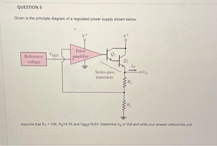
Given is the principle diagram of a regulated power supply shown below.
Reference
voltage
VREF
Error
amplifier
21
Series-pass
transistors
22
www
R₁
R₂
-ovo
Assume that R₁ = 10K, R₂=4.7K and VREF=5.6V. Determine Vo in Volt and write your answer without the unit.
Expert Solution
This question has been solved!
Explore an expertly crafted, step-by-step solution for a thorough understanding of key concepts.

Step by stepSolved in 2 steps with 1 images

Knowledge Booster


Learn more about
Need a deep-dive on the concept behind this application? Look no further. Learn more about this topic, electrical-engineering and related others by exploring similar questions and additional content below.Similar questions
- Book:Operational amplifiers and Linear integrated circuits Chap#03arrow_forwardHello. Please can I have the correct solution to this Electrical Engineering problem in a step by step form. Thanks very much.arrow_forwardDetermine Vx and the mode of operation of the PNP transistor shown in the figure below. Assume Is = °A, B = 50, VA = 00, and Rc = 0.1 KO. 10x10-16 %3D Vcc는 2 V 1.2 V- Rc Select one: a. 0.577 V, Active Mode O b. 0.23 V, Active Mode O c. None of these d. 1.153 V, Active Mode e. 2.306 V, Saturation Modearrow_forward
- 1-) With a +5 V (dc) common mode signal at the input of the circuit in the figure. There is a difference signal in the form of Vdiff = VI1-VI2 = 10*sin (wt) mv. Other in the circuit Assuming the values of the elements (2R1) = 1 ko, R2 = 0.5 MQ, and R3 = R4 = 10 ko, Calculate the voltage values at each node (7 nodes) shown in the figure. A1 RA R2 R3 2R| R3 A3 +. R2 On R4 A2 Un Oarrow_forwardFor the given biasing configuration in figure 5, determine the following parameters: a. IBq- b. Icq c. VCEq. d. Vc . e e. Ve. f. Vb. 16 V 3.9 k2 62 kf 0.68 kQarrow_forwardQ-2: Explain the saturation of a transistor. Find the given unknowns for the figure below. a. Rc. b. Rg c. Rp. d. VCE e. V Also find the voltage V, at cutoff. 12 V 2 mA Rc 7.6 V V B-80 024 V Q-3: Define Lso and lao, How are they related? Find the following f le corresponding to V = +750mv and Va = +5Varrow_forward
- The circuit in Figure below is a BJT common collector amplifier. Obtain expressions for both the voltage gain (AV = Vout / Vin) and the current gain (AI = Iout / I in). Assume Vin >> VBE please need steps explanation so I can understand and learn. thanks in advance Please in typing format pleasearrow_forwardNonearrow_forwardQ3) For the regulator circuit shown in figure below, Vin-15 V, Rs-10 2, Vz-9.1 V, VBE=0.8V, and R=40 2. What are the values of output voltage, input current, the load current, and collector current. 102016 2-8594 Vin R$ Ⓡ R₂ Voutarrow_forward
- 3. For the following circuit assumer, = 33.4 N a. Draw the small signal equivalent circuit. b. Find the input impedance. c. Find output impedance. d. Find the voltage gain. -10 V 68 k2 4.7 kA e. Find the current gain. a = 0.998 10 uSarrow_forwardThe operating point of the npn transistor is defined by a couple of values: Icand Ver- Select one: OTrue O False In the following figure. Q, and Q: are identicaland operate in active mode. if la =9 Icz then V,V2 ICarrow_forward
arrow_back_ios
arrow_forward_ios
Recommended textbooks for you
- Introductory Circuit Analysis (13th Edition)Electrical EngineeringISBN:9780133923605Author:Robert L. BoylestadPublisher:PEARSON
 Delmar's Standard Textbook Of ElectricityElectrical EngineeringISBN:9781337900348Author:Stephen L. HermanPublisher:Cengage Learning
 Programmable Logic ControllersElectrical EngineeringISBN:9780073373843Author:Frank D. PetruzellaPublisher:McGraw-Hill Education
  Fundamentals of Electric CircuitsElectrical EngineeringISBN:9780078028229Author:Charles K Alexander, Matthew SadikuPublisher:McGraw-Hill Education
 Electric Circuits. (11th Edition)Electrical EngineeringISBN:9780134746968Author:James W. Nilsson, Susan RiedelPublisher:PEARSON
 Engineering ElectromagneticsElectrical EngineeringISBN:9780078028151Author:Hayt, William H. (william Hart), Jr, BUCK, John A.Publisher:Mcgraw-hill Education,
Introductory Circuit Analysis (13th Edition)
Electrical Engineering
ISBN:9780133923605
Author:Robert L. Boylestad
Publisher:PEARSON
Delmar's Standard Textbook Of Electricity
Electrical Engineering
ISBN:9781337900348
Author:Stephen L. Herman
Publisher:Cengage Learning
Programmable Logic Controllers
Electrical Engineering
ISBN:9780073373843
Author:Frank D. Petruzella
Publisher:McGraw-Hill Education
Fundamentals of Electric Circuits
Electrical Engineering
ISBN:9780078028229
Author:Charles K Alexander, Matthew Sadiku
Publisher:McGraw-Hill Education
Electric Circuits. (11th Edition)
Electrical Engineering
ISBN:9780134746968
Author:James W. Nilsson, Susan Riedel
Publisher:PEARSON
Engineering Electromagnetics
Electrical Engineering
ISBN:9780078028151
Author:Hayt, William H. (william Hart), Jr, BUCK, John A.
Publisher:Mcgraw-hill Education,