Introductory Circuit Analysis (13th Edition)
13th Edition
ISBN: 9780133923605
Author: Robert L. Boylestad
Publisher: PEARSON
expand_more
expand_more
format_list_bulleted
Concept explainers
Question
thumb_up100%

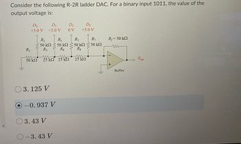
Transcribed Image Text:Consider the following R-2R ladder DAC. For a binary input 1011, the value of the
output voltage is:
Do
D₁
+5.0 V +5.0 V
R₁
• 50 ΚΩ
R₁
R₂
30kn 25km 25 k
03.125 V
-0.937 V
3.43 V
O-3.43 V
D₂
ov
D3
+5.0 V
R₂
R₁
50 kΩ < 50 ΚΩ
R6 Rg
25 ΚΩ
R₁
50 ΚΩ
R,= 50 ΚΩ
www
+
Buffer
Vout
Expert Solution
This question has been solved!
Explore an expertly crafted, step-by-step solution for a thorough understanding of key concepts.
Step by stepSolved in 2 steps with 1 images

Knowledge Booster
Learn more about
Need a deep-dive on the concept behind this application? Look no further. Learn more about this topic, electrical-engineering and related others by exploring similar questions and additional content below.Similar questions
- Which of the following are most true when comparing balanced (differential) signals to unbalanced (single-ended) signals?A. Balanced signals are less susceptible to noise interference.B. Unbalanced signals use fewer wires.C. Balanced signals use ground for one of the two wires.D. Unbalanced signals take advantage of the common-mode rejection capability of op amps.Two correct possible answers.arrow_forward- V2 15Vdo 3 U1A R1 2 1k V- LM324 1k V3 15Vde | VOFF = 0 VAMPL = 1 FREQ = 2k AC = 0 0. R2 Figure 4. Operational amplifier circuit. What frequency does the output voltage (across R3) have? What is the amplitude of the output voltage? From the output waveform and the input waveform, determine the gain of the op-amp circuit. Does this match with what you predicted? How could you change this circuit so that the output voltage would be nearly the same as the input voltage? What purpose would that serve? Can you modify the existing circuit and verify this experimentally? What is the phase difference between the output and input voltage? Derive the transfer function for the output-input relationship for the operational amplifier. How would the gain and the output change if a capacitor were in the feedback path instead of a resistor? (Examine the circuit using phasors and impedance and circuit analysis techniques). -w-arrow_forwardVin R₁ www R₂ www Vout For the given op amp circuit, calculate Vout if R₁ = R2 = 100 2 and vin = 8 V. The value of the output voltage is * V.arrow_forward
- Design and implement a combinational circuit that multiplies by 5 an input decimal digit represented in BCD. The output is also in BCD.arrow_forwardsolve by HAND thanks.arrow_forwardIn Basic electronics lab on summing amplifier Arifa is asked to give the circuit connectionaccording to figure below to make a three input summing amplifier. She uses IC 741 as OP-AMPand two power supplies to power up the IC. According to the instruction of his teacher she usesthree input such that ?1 = 2?, ?3 = −1? & set ?2 such that the output voltage ?0 = −16.5?. A. What is the virtual ground of OP-AMP?B. Draw the equivalent circuit of OP-AMP and then simplify it for Ideal case.C. Determine the value of ?2 from the figure above for which ?0 = −16.5?.D. If the 50KΩ feedback resistor is replaced by a capacitor of 100uF what will be the outputvoltage after 1 second. Use the value of ?2 = 5 ???(200??)?�arrow_forward
- It's urgent please solve quickly.arrow_forwardplease show the step claerlyarrow_forwardSketch the output voltage waveform for each op armp circuits given below. Given the maximum outputvoltage for the op-armp is Vomax = +10 v and Vomin = -10 v.Use input voltage for all circuit as shown. Also use V2 = 4.7 V for D1 and D2. V. 0 -5V- -5V D1 Kt 1K 1K D2 V1 V2arrow_forward
- (d) An instrumentation amplifier is used when the application signal is very low. For the circuit shown in Figure Q2(d), calculate the applied input vin of the circuit to get the output of 5V at vo. Let Rr=360k 2 and R₁ = 12k 52. Rf www R1 Vec www Vo -Vec Figure Q2(d) (e) Illustrates instrumentation system for temperature measurement with the help of block diagram. Vin uA741arrow_forwardA five bit digital to analog converter (DAC) has a voltage output range 0-7 V. The resolution of the converter would be Select one: O a. 0.2000V b. 0.5333V c. 1.28571V d. 0.22581Varrow_forwardi need the answer quicklyarrow_forward
arrow_back_ios
SEE MORE QUESTIONS
arrow_forward_ios
Recommended textbooks for you
 Introductory Circuit Analysis (13th Edition)Electrical EngineeringISBN:9780133923605Author:Robert L. BoylestadPublisher:PEARSON
 Delmar's Standard Textbook Of ElectricityElectrical EngineeringISBN:9781337900348Author:Stephen L. HermanPublisher:Cengage Learning
 Programmable Logic ControllersElectrical EngineeringISBN:9780073373843Author:Frank D. PetruzellaPublisher:McGraw-Hill Education
 Fundamentals of Electric CircuitsElectrical EngineeringISBN:9780078028229Author:Charles K Alexander, Matthew SadikuPublisher:McGraw-Hill Education
 Electric Circuits. (11th Edition)Electrical EngineeringISBN:9780134746968Author:James W. Nilsson, Susan RiedelPublisher:PEARSON
 Engineering ElectromagneticsElectrical EngineeringISBN:9780078028151Author:Hayt, William H. (william Hart), Jr, BUCK, John A.Publisher:Mcgraw-hill Education,

Introductory Circuit Analysis (13th Edition)
Electrical Engineering
ISBN:9780133923605
Author:Robert L. Boylestad
Publisher:PEARSON

Delmar's Standard Textbook Of Electricity
Electrical Engineering
ISBN:9781337900348
Author:Stephen L. Herman
Publisher:Cengage Learning

Programmable Logic Controllers
Electrical Engineering
ISBN:9780073373843
Author:Frank D. Petruzella
Publisher:McGraw-Hill Education

Fundamentals of Electric Circuits
Electrical Engineering
ISBN:9780078028229
Author:Charles K Alexander, Matthew Sadiku
Publisher:McGraw-Hill Education

Electric Circuits. (11th Edition)
Electrical Engineering
ISBN:9780134746968
Author:James W. Nilsson, Susan Riedel
Publisher:PEARSON

Engineering Electromagnetics
Electrical Engineering
ISBN:9780078028151
Author:Hayt, William H. (william Hart), Jr, BUCK, John A.
Publisher:Mcgraw-hill Education,