Introductory Circuit Analysis (13th Edition)
13th Edition
ISBN: 9780133923605
Author: Robert L. Boylestad
Publisher: PEARSON
expand_more
expand_more
format_list_bulleted
Concept explainers
Question

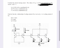
Transcribed Image Text:Consider the current steering circuit. The values of Iref, I2 and I6 are mentioned on the
circuit . Let B= o.
Let 14.28% of I6 is contributed by Q3
28.57% of Ig is contributed by Q4
57.14% of Is is contributed by Qs
Find out the ratio , relationship of scaling current of Q2, Q3. Q4 .Q5 W.r.t scaling current of
Q1.
Iref =1.5mA
I=4.5mA
I6=10.5mA
VcC
VCC
Iref=1.5mA
R1
12= 4.5mA
1 kQ
Q2
Q3
Q4
Q5
Q1
I3
15
16-10.SmA
Expert Solution
This question has been solved!
Explore an expertly crafted, step-by-step solution for a thorough understanding of key concepts.
This is a popular solution
Trending nowThis is a popular solution!
Step by stepSolved in 2 steps with 2 images

Knowledge Booster
Learn more about
Need a deep-dive on the concept behind this application? Look no further. Learn more about this topic, electrical-engineering and related others by exploring similar questions and additional content below.Similar questions
- Draw and label a voltage divider that generates0.5V from an input of 1.5V. Then draw and label a current divider that generates 1.25A from an input of1.0A. Pleaseclearlydefine/label the value of all variables (e.g. resistances). If a solution does not exist, then simply state so.arrow_forwardProblem 4: Given the circuit below, determine the value of V2 so the output waveform is always positive. Explain how this circuit works. V1 8Vpk 2kHz 0.⁰ V2 40 4.7kQ D1 Voutarrow_forwardI need some help solving this: I found the measured resistance to be R1=980, R2=982 and R3=490. I need to use these values to calculate the reference current and the output current of the widlar current source. I know the formula for the reference current is: (V-Vbe)/R1 Im not sure what the formula for output current is nor how to solve for it. How would I go about solving this and is my reference current formula correct?arrow_forward
- V₁ www R3 V Ru RS www Here - V₁ = 5.8V, V2=5.2V, V3 = 6.70, V4 = 5.10 V5 = 7.7V R₁ = 19 KR, R₂ = 79KR, R3 = 49KR R72 KR, R = 46 KR what is the voltage Vn at inverting terminal of the pamp. 15arrow_forwardwrite in to hand notearrow_forwardIn the circuit , the voltage across the 4 ohm resistor in volts is ___ The circuit is equivalent to a 12V source in series with how many ohms ofresistance? In the circuit, the current through the 6 ohm resistor in amps is ___arrow_forward
- Do not copy from other websites Correct and detailed answer will be Upvoted else downvoted. Thank you!arrow_forwardYour friend who works for Photons 'R Us wants help with a circuit to drive the new LED his company has developed. He wants to turn on the LED based on a digital signal which swings between VDD and OV. Unfortunately the LED when it is on drops a voltage VD across of it and requires a current of IL to flow through it to produce light. You ask your 10A Professor for help and he shows you two circuits shown in figure 5, of course in his usual absent-minded self does not tell you how each one works, he only cryptically says one inverts and the other does not. V₁ V DD R₁ (a) Configuration A Vo VDD Figure 5: LED Driver RL (b) Configuration B (a) Based on your 10A knowledge which circuit will turn the LED on when the digital signal is logic 1 ? Explain your answer clearlyarrow_forwardcuicuit designed in winknown isubuenit, va resistance R = 2.8K2 and two identical silicon BITS T1 and 12 with 72 and T2 with forward gains BF = 200. The supply voltage Vcc =-25 volts Vcc=25 volts Sub-circuit JICA T2 IB₁1 IB12 VIR R = 28K2 VIC, 2 GIND IB, 1 and Ic, s designate the base and collector current of T2 vespectively where as the courrents IB,₁2 and IG2 designate the base and the collector currents of T2 respectively. T2 and 12 operate in forward active mode Assume that IB, 1 and IB₁2 are equal · VBE, on = 0.8 molt (Threshold woltage) (a) What is the value of the current IR through vesistance R.? (MA) (b) what is the value of the base vaurrent IB, 1? (MA) (c) what is the value of the collector Ic₁₁? (MA) (d) The evicuit idesigned using Resistance Rand Transistors T₁ and To performs an electronic function to connect to sub circut which function is it?arrow_forward
arrow_back_ios
arrow_forward_ios
Recommended textbooks for you
 Introductory Circuit Analysis (13th Edition)Electrical EngineeringISBN:9780133923605Author:Robert L. BoylestadPublisher:PEARSON
 Delmar's Standard Textbook Of ElectricityElectrical EngineeringISBN:9781337900348Author:Stephen L. HermanPublisher:Cengage Learning
 Programmable Logic ControllersElectrical EngineeringISBN:9780073373843Author:Frank D. PetruzellaPublisher:McGraw-Hill Education
 Fundamentals of Electric CircuitsElectrical EngineeringISBN:9780078028229Author:Charles K Alexander, Matthew SadikuPublisher:McGraw-Hill Education
 Electric Circuits. (11th Edition)Electrical EngineeringISBN:9780134746968Author:James W. Nilsson, Susan RiedelPublisher:PEARSON
 Engineering ElectromagneticsElectrical EngineeringISBN:9780078028151Author:Hayt, William H. (william Hart), Jr, BUCK, John A.Publisher:Mcgraw-hill Education,

Introductory Circuit Analysis (13th Edition)
Electrical Engineering
ISBN:9780133923605
Author:Robert L. Boylestad
Publisher:PEARSON

Delmar's Standard Textbook Of Electricity
Electrical Engineering
ISBN:9781337900348
Author:Stephen L. Herman
Publisher:Cengage Learning

Programmable Logic Controllers
Electrical Engineering
ISBN:9780073373843
Author:Frank D. Petruzella
Publisher:McGraw-Hill Education

Fundamentals of Electric Circuits
Electrical Engineering
ISBN:9780078028229
Author:Charles K Alexander, Matthew Sadiku
Publisher:McGraw-Hill Education

Electric Circuits. (11th Edition)
Electrical Engineering
ISBN:9780134746968
Author:James W. Nilsson, Susan Riedel
Publisher:PEARSON

Engineering Electromagnetics
Electrical Engineering
ISBN:9780078028151
Author:Hayt, William H. (william Hart), Jr, BUCK, John A.
Publisher:Mcgraw-hill Education,