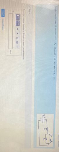
Consider the circuit shown. The component values are Vo = 10Volts, R =8 2. R= 40, and Ry = 42. %3D %3D Part A Determine the power dissipated by Rz when the switch S is open as shown. Watts Submit Request Ans wer
Q: 10.0 pF 3. In the circuit below each capacitor initially has a charge of magnitude 3.50 nC on its…
A: Given data : Capacitor's initial charge, q=3.50 nC=3.50×10⁻⁹ C Energy loss is 80%, ∴Ef=0.2Ei…
Q: R₁ = 19 ε = 12V b C ww R₂ = 29 ww d R₂ = 30 e g f Use Kirchhoff's Law to solve for the current,…
A: As per our company guidelines we are supposed to answer only first 3-sub part. Kindly repost other…
Q: What is the voltage across R5 of the circuit shown below ? R, = 200 R2 = 200 R3 = 120 R4 = 120 R5 =…
A:
Q: Determinea. Ceg, b. qeg. 91, 92, 93 c. V, V2 and V30of the given illustration below. C2 2F 4F 6F V =…
A:
Q: The voltage-current phasor diagram shown in the picture is for a + AC circuit. Vo wt
A: According to the figure shown, the voltage leads the current.
Q: Problem 7: A TV works properly under the voltage of AV = 210 V with power P= 1500 W. Part (a)…
A:
Q: R2 R1 R3 R4 V Rs R6 In the above circuit, R1 = 100, R2 = 200, R3 = 150, R4 = 50, RS5 = 300 and R6 =…
A:
Q: Use (sheet no. 13) in the attached excel file and the following equation RL PRL = e? (R2 + R)² data…
A: This question can be solved by using the basic concept of AC circuit .
Q: Two input waveforms given in Figure 2 are applied at RC circuit, draw the output waveforms across…
A: There are two independent questions posted. Only 1 question can be solved per session. Please…
Q: C. The emf of the ideal battery is V= 100 V in the following figure and resistances values are…
A: 1. The total resistance of the circuit is calculated as shown below.…
Q: R, = 100 N R = 100 N E V, = 6V I V. = 4.5 V V, = 36 V R = 1.2 kf V = 18 V R, = 120 2 V, = 5.4 V V =…
A:
Q: 3 When switch S in Fig. E25.29 Figure E25.29 is open, the voltmeter V reads 3.08 V. When the switch…
A:
Q: In a RC circuit with power supply with an emf of 20 V. capacitance 3 uF, and resistance 1000 Q, the…
A: Given : Emf = 20 VCapacitance = 3 μF =3×10 -6 FResistance =1000 Ω
Q: In the above circuit, R, = 100, R2 = 400, R3 = 300, R4 = 200, R5 = 60O. The battery voltage is 12V.…
A: Free electrons can flow through a conductor causing electrical current. When electrons flow through…
Q: 1. Figure-1 shows, Vs= 10V, internal resistance, R-100 Q, Find the circuit current and current…
A:
Q: In Figure 04, assume that the load is purely resistive (RL), determine the value of the load…
A:
Q: The switch in Figure P27.51a closes when AV, > voltmeter reads a potential difference as plotted in…
A: Given: WHen charging, time constant T =Req C = (R1 +R2 ) CVoltage across capacitor at any…
Q: R Sliding contact Ro The figure above shows a battery connected across a uniform resistor Ro. A…
A: Through an electrochemical oxidation-reduction reaction (redox), a battery converts chemical energy…
Q: 60V 4. Determine the unknown RESISTANCE in the circuit below. 6802 Te 1.Ok 30mA R5 mis 270-2 R4 v R₂…
A:
Q: Don't use chatgpt will upvote Need help Please be quick as soon as possible
A: Solution(a)If we reduce the value of the capacitor C1 this will affect the high-pass filter formed…
Q: Consider the following cireuit: DDDD G. a. Write the truth table for G(X.YZ). b. Convert the circuit…
A: Given, Logic gate is, So, truth table for output G(X,Y,Z), Input Output X Y Z G 0 0 0 0…
Q: Determine the admittance Yfor the circuit given in the figure. Take R= 4 Q. j8Q +-j10 2 R The…
A: Given R = 4 Ω Find the admittance Y, as following below.
Q: Use Super Position theorem to find the current flowing through Resistance(Rf) and also voltage…
A:
Q: (a) Find the time constant of the circuit. S (b) Find the maximum charge on the capacitor after the…
A:
Q: An RC circuit consisting of a resistor and capacitor is known to have a time constant of 0.800 s.…
A: Given that,Time constant : RC = τ = 0.800 (sec)Here we need to find the accumulation of charge on…
Q: In an RC series circuit, emf = 12.0 V, resistance R= 1.21 MQ, and capacitance C= 1.87 µF. Find the…
A: Given that,Capacitance : C = 1.87 (μF)Resistnace : R = 1.21 (M Ohm)EMF : E = 12 (V)Here we need to…
Q: Consider the following circuit. R Which of the following configurations do you use to measure…
A: To find :) which of the configuration measures the current and which one measure voltage.
Q: 3. Four capacitors are connected to an EMF as shown with C₂ = 20 μF, C₂ = 4 μF, C₂ = 3 μF, and C₁ =…
A:
Q: The Q vs t graph shown below is for the capacitor of an RC circuit. Q (C) 18 13.5 9. 4.5 Determine…
A: From the graph, The maximum current is Qm=0.9×19 C=17.1 C where 0.9 is the measure of the unit box…
Q: An 8-bit DAC has a Vref of 12 V. The binary input is 10111011. Find the analog output voltage.
A:
Q: RI R3 RS Vi R2 v2
A:
Q: R R S R In the circuit above, the battery has emf
A:
Q: R Rs R. ww Re In the above circuit, R1 = 100, R2 = 200. R3 = 150, R4 = 50, RS = 300 and R6 = 400 The…
A:
Q: Given a parallel circuit with three resistors and a total voltage of 15, R1 = 10 Q, R2 = 20 Q, and…
A:
Q: 2. An RC circuit is pictured. a. Find the current at time t-o. b. Find the current at time t-0.10 s…
A: (a)The equation to find the voltage across the capacitor at a time t while the capacitor is…
Q: Q.2 An Op Amp network is given in the figure below. Find out the output voltages V2 and V3. 200 KL V…
A: A virtual ground is result of an op-amp trying to keep its two input terminals at the same potential…
Q: R2 R1 R3 R4 V Rs R6 In the above circuit, R1 = 102, R2 = 20N, R3 = 152, R4 = 50, R5 = 300 and R6 =…
A: We are authorized to answer three subparts at a time, since you have not mentioned which part you…
Q: In the circuit below, C1 = 10.0 µF and C, = 30.0 pF are initially uncharged. First the switch is…
A:
Q: K, and a generator of voltage V. Mark as true or false the following statements concerning the stor…
A: We have to mark true or false for the given statements concerning the realtive phase of V, VL, Vr,…
Q: R1 R, R3 R Rs In the above circuit, R1 = 102, R2 = 402, R3 = R4 = 202, R5 = 602. The battery voltage…
A: Given data- R1=10 ohmR2=40 ohmR3=30 ohmR4=20 ohmR5=60 ohmV=12 V
Q: 3. Four capacitors are connected to an EMF as shown with C₂ = 20 μF, C₂ = 4μF, C₂ = 3 μF, and C₁ = 4…
A: The circuit diagram is given belowFrom the circuit, we can observe that, the capacitors C1 and C3 is…
Trending now
This is a popular solution!
Step by step
Solved in 2 steps with 2 images