
Introductory Circuit Analysis (13th Edition)
13th Edition
ISBN: 9780133923605
Author: Robert L. Boylestad
Publisher: PEARSON
expand_more
expand_more
format_list_bulleted
Related questions
Question
thumb_up100%
I need help solving the table on part 3.
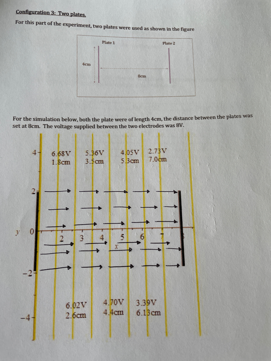

Transcribed Image Text:Configuration 3: Two plates.
For this part of the experiment, two plates were used as shown in the figure
Plate 1
Plate 2
4cm
Scm
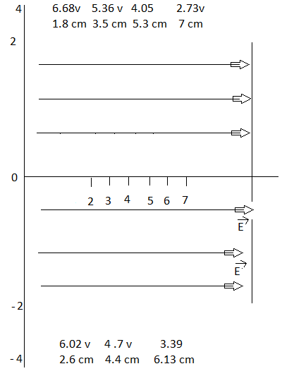
For the simulation below, both the plate were of length 4cm, the distance between the plates was
set at 8cm. The voltage supplied between the two electrodes was 8V.
6.68V
5.36V
4.05V
2.73V
1.8cm
3.5cm
5.3cm
7.0cm
6.02V
4.70V
3.39V
2.бсm
4.4cm
6.13cm
5.
2.

Transcribed Image Text:Instructions:
1. Print the page above, and draw the electric field lines
2. Which electrode was connected to the +ve terminal?
ANS:
3. Using the above simulation, the following data table was generated, calculate the electric
field between the electrodes and complete the table below.
Electric field (V/cm)
D. ४२५ णCn
0.733 110m
0.733 VICM
0.722 VICM
0.825 VIm
0733 Vlim
x-position (cm)
Voltage (V)
6.68
1.8
2.6
6.02
5.36
3.5
4.4
4.70
4.05
3.39
5.3
6.1
7.0
2.73
E = V- Ui
E=-16.02-6.66)
- 0.825
V/um
(२.6 - ।.४
Expert Solution
arrow_forward
Step 1
Ans 1 .
The direction of electric field lines are shown below in the diagram :

Step by stepSolved in 4 steps with 2 images

Knowledge Booster

Similar questions
- Need help on problem “a” . If possible can you show me how to do it step by step . Thanks in advance . The songs choices don’t really matter , whichever two you picked is fine by me.arrow_forwardNOTE: Solve this as soon as possible, I need this urgently Find the current R, = 3.00 N R = 3.00 R2 = 3.00 N R = 4.00 N V1 = 24.00 V V2 = 29.00 Varrow_forwardplease show me how to solve this without nodal analysis, i have to solve this in stages redrawing the circuit. thank you.arrow_forward
- r=8arrow_forward1. Type of circuit? 2. What is the total resistance? 3. What is current flow through R1 and R2 ? 4. What is voltage across R1 and R2 ?arrow_forwardProblem #5:> You HAVE A CollectiON. OF ONLY 1002 and 102 Rosisions. DosyN A CIRCUIT WHOSE Rey = 2652. You MUST USE the Minimum NUMBER OF RESISTORS,arrow_forward
arrow_back_ios
arrow_forward_ios
Recommended textbooks for you
- Introductory Circuit Analysis (13th Edition)Electrical EngineeringISBN:9780133923605Author:Robert L. BoylestadPublisher:PEARSON
 Delmar's Standard Textbook Of ElectricityElectrical EngineeringISBN:9781337900348Author:Stephen L. HermanPublisher:Cengage Learning
 Programmable Logic ControllersElectrical EngineeringISBN:9780073373843Author:Frank D. PetruzellaPublisher:McGraw-Hill Education
  Fundamentals of Electric CircuitsElectrical EngineeringISBN:9780078028229Author:Charles K Alexander, Matthew SadikuPublisher:McGraw-Hill Education
 Electric Circuits. (11th Edition)Electrical EngineeringISBN:9780134746968Author:James W. Nilsson, Susan RiedelPublisher:PEARSON
 Engineering ElectromagneticsElectrical EngineeringISBN:9780078028151Author:Hayt, William H. (william Hart), Jr, BUCK, John A.Publisher:Mcgraw-hill Education,
Introductory Circuit Analysis (13th Edition)
Electrical Engineering
ISBN:9780133923605
Author:Robert L. Boylestad
Publisher:PEARSON
Delmar's Standard Textbook Of Electricity
Electrical Engineering
ISBN:9781337900348
Author:Stephen L. Herman
Publisher:Cengage Learning
Programmable Logic Controllers
Electrical Engineering
ISBN:9780073373843
Author:Frank D. Petruzella
Publisher:McGraw-Hill Education
Fundamentals of Electric Circuits
Electrical Engineering
ISBN:9780078028229
Author:Charles K Alexander, Matthew Sadiku
Publisher:McGraw-Hill Education
Electric Circuits. (11th Edition)
Electrical Engineering
ISBN:9780134746968
Author:James W. Nilsson, Susan Riedel
Publisher:PEARSON
Engineering Electromagnetics
Electrical Engineering
ISBN:9780078028151
Author:Hayt, William H. (william Hart), Jr, BUCK, John A.
Publisher:Mcgraw-hill Education,