Concept explainers
Project 5:
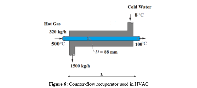
Automobile radiator, condenser, evaporator, air preheater, and cooling tower are common types of direct heat exchangers that also called recuperators. Recuperators may have different types based on the flow arrangement of the hot and cold fluid. Your role in a company that manufactures recuperators heat exchanger is to design a counter-flow recuperator (see Figure.6) that is used in heating, ventilation, and air conditioning (HVAC).
Section.1:
− Exhaust pipe is 88 ?? diameter.
− Exhaust gas enters at 500??.
− Water jacket is used and enters at 8??.
− The surface heat coefficient of water and gas are ℎ????? = 300 ?/(?2.?) and ℎ??? = 1500 ?/(?2.?) , respectively.
− Assume conduction transfer through wall is negligible.
− The gas heat specific capacity is ?? is 1130 ?/(??.?).
− The water heat specific capacity is ?? is 4190 ?/(??.?).
− The flow rate of gas and water are 320 and 1500 ??/h, respectively.
− The gas must be cooled to 100??.
You need to design a counter-flow recuperator by calculating the required length of pipe.

Step by stepSolved in 3 steps with 3 images

- Shown below is a heat exchanger used to cool down the liquid in the tube. The shell is well insulated. (1) If the tube is selected as the system, select the correct energy balance equation._____________ A. B. C. D.arrow_forwardShown below is a heat exchanger used to cool down the liquid in the tube. The shell is well insulated. (2) If inner walls of the shell are system boundaries, and liquids within system boundaries (the liquid between the shell and tube and the liquid in the tube) are chosen as the system, select the correct energy balance equation._____________ A. B. C. D.arrow_forwardThermodynamics -heat transfer. Show complete workarrow_forward
- 3. For the gas system power illustrated in Figure 3 (with the air-standard analysis assumptions), calculate thermal efficiency, back work ratio, and Weycle -10 P₁ = 100 kPa T₁ = 350 K Oia Heat exchanger Heat exchanger Qout T₁ - 1500 K Turbine Wycle 1 T₁ - 1500 K p= 1000 kPa p= 100 kPa T₁ = 350 K Figure 3. Operating condition of a gas power system cycle (The P-V and T-S diagram)arrow_forwardHandwritten -HTarrow_forward| Part of a refrigeration system operates at steady state with Refrigerant 22 as shown in the figure below. There is no significant heat transfer to or from the heat exchanger, valve, and piping. Kinetic and potential energy effects are negligible. State 1 is a saturated liquid. What temperature is it, in °F? Describe the refrigerant at state 4 as one of the following: compressed liquid, saturated liquid, tyro-phase mixture, saturated vapor, or superheated vapor. Determine the required mass flow for the given operating conditions, in lb/min. Determine the rate of heat transfer between the evaporator and its surroundings, in b. Btu/min. Make sure to clearly state the direction of heat transfer. 1. T=10°F P= 15 Ibf in (AV), = 9.5 ft/min. Pi= 120 Ibf/in.? Heat exchanger Throttling valve Evaporator P 15 lbfin.2 X3 = 1.0 P2= 15 lbf/in.2arrow_forward
- Problem 2: Win High-pressure liquid water (Pump Boiler Condenser à out Low-pressure liquid water FIGURE 7-1 Example of a power cycle. High-pressure steam 3 Turbine Wout Low-pressure superheated vapor or high-quality two-phase mixture A simple steam power cycle consists of a boiler, turbine, condenser, and pump as shown in the sketch above. All the heat removal in the cycle is done by the condenser which transfers the heat to pipes carrying cooling water. The cooling water has a mass flow rate of 7 kg/sec, and a specific heat of 4,180 J/kg-°C. The cooling water is supplied at a temperature of 10 °C and exits at 20 °C. Heat is supplied to the cycle through a steam boiler at a rate, Ċin = 420 kW. Find the following: a. The rate at which heat is rejected from the cycle to the cooling water, Qout- b. The net power produced in kilowatts, Wnet- c. The cycle efficiency, cycle.arrow_forwardPlease find the highest thermal efficiency possible, while remaining within the boundaries. What is required: -Power produced must be at least 60 Mega Watts -Thermal efficiency must be greater than 36% -Back-work ratio must be smaller than 48% Assume: -air is the working fluid -specific heats vary with temperature (use table A-17) -Compressor inlet is at 1atm and 300k -the combustion process is isobaric and is modeled as a heat exchanger -Turbine exhaust is the same pressure as compressor inlet Compressor specifics: -Max volume flow rate (m^3/h) = 600,000 -Max outlet pressure (atm) = 12 -Isentropic efficiency = 90% Combustion chamber and gas tubine specifics (Note these come as a set) -Max pressure = 16.7 atm -Max temp = 1500 (celcius) -Turbine isentropic efficiency = 92% -Max heat rate = 230MWarrow_forwardDetermine the compressor work, W,comp. And the condenser heat transfer, Qc.arrow_forward
 Elements Of ElectromagneticsMechanical EngineeringISBN:9780190698614Author:Sadiku, Matthew N. O.Publisher:Oxford University Press
 Mechanics of Materials (10th Edition)Mechanical EngineeringISBN:9780134319650Author:Russell C. HibbelerPublisher:PEARSON
 Thermodynamics: An Engineering ApproachMechanical EngineeringISBN:9781259822674Author:Yunus A. Cengel Dr., Michael A. BolesPublisher:McGraw-Hill Education
 Control Systems EngineeringMechanical EngineeringISBN:9781118170519Author:Norman S. NisePublisher:WILEY
 Mechanics of Materials (MindTap Course List)Mechanical EngineeringISBN:9781337093347Author:Barry J. Goodno, James M. GerePublisher:Cengage Learning
 Engineering Mechanics: StaticsMechanical EngineeringISBN:9781118807330Author:James L. Meriam, L. G. Kraige, J. N. BoltonPublisher:WILEY


