Introductory Circuit Analysis (13th Edition)
13th Edition
ISBN: 9780133923605
Author: Robert L. Boylestad
Publisher: PEARSON
expand_more
expand_more
format_list_bulleted
Question

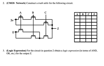
Transcribed Image Text:2. (CMOS Network) Construct a truth table for the following circuit.
3v
0
A
B
C
-Z
ABCZ
3. (Logic Expression) For the circuit in question 2 obtain a logic expression (in terms of AND,
OR, etc.) for the output Z.
Expert Solution
This question has been solved!
Explore an expertly crafted, step-by-step solution for a thorough understanding of key concepts.
Step by stepSolved in 4 steps with 7 images

Knowledge Booster
Learn more about
Need a deep-dive on the concept behind this application? Look no further. Learn more about this topic, electrical-engineering and related others by exploring similar questions and additional content below.Similar questions
- 5 Question 6 Given the following SOP: Ea.3.5.67) F = Implement the SOP using the 74138 decoder given below and two inputs AND/NAND gates, the datasheet of the decoder is available here U1 YO Y2 Y3 Y4 Y5 Y6 Y7 G1 -G2A -G2B 74LS138N 21204arrow_forwardThe final equation for the first part should be in SOP form. the circuit should be drawn using NANDs and inverters onlyarrow_forward3.5 Design minimal two-level AND-OR and NAND-NAND realizations of the following logic function. Draw circuit diagrams. g (a, b, c, d) =[]M(2, 3, 6, 8, 9, 12)arrow_forward
- Construct a Truth Table on the Following CMOS Circuitarrow_forwardWrite out the truth table for the following CMOS circuits: Vdd C- A- Вarrow_forwardCreate a schematic diagram and Truth Table for a logic circuit that is made up entirely of NAND gates of the given below:The scenario involves a circuit that has an alarm system, which activates a buzzer whenever both the power and at least one of the two sensors are turned on. It is important to note that the sensors will only function if an enable pin is activated.arrow_forward
- Implement NOR-NOR and NAND-AND simplify,show with a K-map and logic diagram. F(A,B,C,D) = (0,1,2,3,4,8,9,12)arrow_forwardPlease answer question 5 in the image. With details on how to do it. Also please make handwriting legible and clear to understand. Thank you.arrow_forward1) Half wave bridge inverter have following construction find the output signal sequencly depending on the through table(S1*,S2 S1,S2- S1,S2*----S1*,S2*) if the input DC voltage 60 V Load To Co 2) Explaine the power root ofH.W inverter in full load inductance 3) Whts the roal of Dland D2 in power flow voltage ion onplicationarrow_forward
arrow_back_ios
arrow_forward_ios
Recommended textbooks for you
 Introductory Circuit Analysis (13th Edition)Electrical EngineeringISBN:9780133923605Author:Robert L. BoylestadPublisher:PEARSON
 Delmar's Standard Textbook Of ElectricityElectrical EngineeringISBN:9781337900348Author:Stephen L. HermanPublisher:Cengage Learning
 Programmable Logic ControllersElectrical EngineeringISBN:9780073373843Author:Frank D. PetruzellaPublisher:McGraw-Hill Education
 Fundamentals of Electric CircuitsElectrical EngineeringISBN:9780078028229Author:Charles K Alexander, Matthew SadikuPublisher:McGraw-Hill Education
 Electric Circuits. (11th Edition)Electrical EngineeringISBN:9780134746968Author:James W. Nilsson, Susan RiedelPublisher:PEARSON
 Engineering ElectromagneticsElectrical EngineeringISBN:9780078028151Author:Hayt, William H. (william Hart), Jr, BUCK, John A.Publisher:Mcgraw-hill Education,

Introductory Circuit Analysis (13th Edition)
Electrical Engineering
ISBN:9780133923605
Author:Robert L. Boylestad
Publisher:PEARSON

Delmar's Standard Textbook Of Electricity
Electrical Engineering
ISBN:9781337900348
Author:Stephen L. Herman
Publisher:Cengage Learning

Programmable Logic Controllers
Electrical Engineering
ISBN:9780073373843
Author:Frank D. Petruzella
Publisher:McGraw-Hill Education

Fundamentals of Electric Circuits
Electrical Engineering
ISBN:9780078028229
Author:Charles K Alexander, Matthew Sadiku
Publisher:McGraw-Hill Education

Electric Circuits. (11th Edition)
Electrical Engineering
ISBN:9780134746968
Author:James W. Nilsson, Susan Riedel
Publisher:PEARSON

Engineering Electromagnetics
Electrical Engineering
ISBN:9780078028151
Author:Hayt, William H. (william Hart), Jr, BUCK, John A.
Publisher:Mcgraw-hill Education,