Mechanics of Materials (MindTap Course List)
9th Edition
ISBN: 9781337093347
Author: Barry J. Goodno, James M. Gere
Publisher: Cengage Learning
expand_more
expand_more
format_list_bulleted
Concept explainers
Question

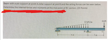
Transcribed Image Text:Beam with a pin support at point A,roller support at pint B and the acting forces can be seen below.
Determine the internal forces and moments at the mid point of BC section. (20 Points)
6 m
12 kN/m
B
3 m
6 kN
Expert Solution
This question has been solved!
Explore an expertly crafted, step-by-step solution for a thorough understanding of key concepts.
Step by stepSolved in 3 steps with 2 images

Knowledge Booster
Learn more about
Need a deep-dive on the concept behind this application? Look no further. Learn more about this topic, mechanical-engineering and related others by exploring similar questions and additional content below.Similar questions
- 3 For the beam shown, find the reactions at the supports and plot the shear-force and bending-moment diagrams. V = 9 kN, V2 = 9 kN, V3 = 200 mm, and V4 = 1100 mm. ATAT-V3 Provide values at all key points shown in the given shear-force and bending-moment diagrams. X (mm) B A = B = C = D = E= F= P = Q = E * KN * KN * KN × KN KN x KN ✩ kN.mm *kN.mm D 0.00 Reaction force R₁ (left) = In the shear-force and bending-moment diagrams given, +V 0.00 X (mm) 6.3 kN and reaction force R2 (right) = P 11.7 kN. Q 0.00arrow_forwardNeed help please include all units and steps. Thanksarrow_forwardThe column shown is fabricated from two C250 x 30 standard steel shapes (see Appendix B for its cross-sectional properties) that are oriented back-to-back with a gap of 33 mm between the two channels. The column is fixed at its base and free to translate in the y direction at its upper end. Translation in the z direction, however, is restrained at its upper end. A load P is applied at an offset distance of 430 mm from the channel flanges. Use the AISC equations given in Section 16.5, and assume that L = 4.1 m, s = 33 mm, E = 200 GPa, oy = 275 MPa, and (Gallow); = 145 MPa. Offset - distance e P Lateral bracing in z direction C250 x 30 L C250 x 30 Cross section.arrow_forward
- Solve for the sum of moment of all forces clockwise direction is positive at point A, B, I & D. Include all moments. JOON 2m G 8ON 2m 2m R= 90N 2m 2m P= 120N 2m 2m 2marrow_forward4. Determine the force at roller B if a 15 mm gap resulted from a construction error. Compare the maximum moment in the beam to the case if no gap existed. The steel beam is a W250x32.7 16 kN/m B 15 mm 4 m 6 marrow_forwardBelow Figure shows the section of an angle purlin. A bending moment of 5 kN.m is applied to the purlin in a plane at an angle of 30 deg to the vertical y axis. If the sense of the bending moment is such that both its components Mx and My produce tension in the positive xy quadrant, calculate the maximum direct stress in the purlin, stating clearly the point at which it acts. * 100 mm E 10mm 30 C D -10mm 57 MPa. 89 MPa. Non Above O 72 MPa. 125mmarrow_forward
- Draw a FBD of section CD. Do not solve the rest of the problemarrow_forwardIn the crane shown, assume that the horizontal arm of the crane weighs 200 kg/m. If a counterweight of 100kN is used, what is the capacity P of the crane? Also find the moment at the base of the crane when no load is being carried (i.e., when P=0). What weight should be added so that the capacity would rise to 8 tons? 130 On-arrow_forwardSee attachedarrow_forward
- Solve the following structure for the forces in member AB and draw and label a free-body-diagram for AB with the pins removed (ie show the forces in member AB). Show all work done pleasearrow_forwardF -1.5 m -1.5 m |A 1 m M 45° Determine the support reactions on the member in Fig. The collar at A is fixed to the member and can slide vertically along the vertical shaft. If F=856 N and M=590 N-m Find the Moment at point A, include the rotation in your answer.arrow_forwardParrow_forward
arrow_back_ios
SEE MORE QUESTIONS
arrow_forward_ios
Recommended textbooks for you
 Mechanics of Materials (MindTap Course List)Mechanical EngineeringISBN:9781337093347Author:Barry J. Goodno, James M. GerePublisher:Cengage Learning

Mechanics of Materials (MindTap Course List)
Mechanical Engineering
ISBN:9781337093347
Author:Barry J. Goodno, James M. Gere
Publisher:Cengage Learning