Elements Of Electromagnetics
7th Edition
ISBN: 9780190698614
Author: Sadiku, Matthew N. O.
Publisher: Oxford University Press
expand_more
expand_more
format_list_bulleted
Concept explainers
Question
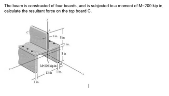
The beam is made up of four boards, and is subjected to a moment of M=200 kip in, calculate the resultant force on
the top board C.

Transcribed Image Text:The beam is constructed of four boards, and is subjected to a moment of M=200 kip in,
calculate the resultant force on the top board C.
-1 in.
1 in.
M-200 kip.in
13 in
80
T
in.
8 in
1 in.
Expert Solution
This question has been solved!
Explore an expertly crafted, step-by-step solution for a thorough understanding of key concepts.
Step by stepSolved in 3 steps

Knowledge Booster
Learn more about
Need a deep-dive on the concept behind this application? Look no further. Learn more about this topic, mechanical-engineering and related others by exploring similar questions and additional content below.Similar questions
- 4. Determine the force at roller B if a 15 mm gap resulted from a construction error. Compare the maximum moment in the beam to the case if no gap existed. The steel beam is a W250x32.7 16 kN/m B 15 mm 4 m 6 marrow_forwardDetermine the bending moment at point D if F₁ = 499 lb, F₂ = 263 lb, and F3 = 307 lb. -6 ft- F1 C 1.17. F2 B D -4ft-4ft-6 ft- 12 ft F3 Earrow_forwardDetermine the magnitude of the vertical force Cy for the cantilever beam, where P = 29 kips and M = 40 kip-ft. A 3.5 ft O 21 kips O 25 kips 42 kips 18 kips 29 kips M B 6.5 ftarrow_forward
- Find an expression for the moments at the fixed supports for the beam shownarrow_forwardThe answer must be 23.88 Kipsarrow_forwardDetermine the resultant of the distributed load acting on the beam shown, and locate its line of action with respect to the support. The loads applied are wz = 230 lb/ft and w2 = 35 lb/ft. The dimensions on the figure are a = 5.6 ft, and b = 2.5 ft. w, Fresultant Ib %3D ft Cline-of-action =arrow_forward
- 0.28. The tire wrench shown in the accompanying figure is used to tighten the bolt on a wheel. Given the infor- mation on the diagram, determine the moment about point O for the two loading situations shown: a. pushing perpendicular to the wrench arm b. pushing at a 75° angle, as shown F =250 N 75 -L=1m- Problem 10.28arrow_forward9) Assume the rod has a fixed support at C. The fixed support can resist a moment about each axis and a force. Translate the origin of the X, Y and Z axes to point C. Assume the x axis is along the center of the rod before the bend. Assume the forces at the end of the bent rod act at the centroid of the face. Give answers for forces in Ib and moment in Ib in. B 3 in 75 lb 8 in. 3 in. 100 lb 80 lb units: Ib %3D Cy =, M %3D Cxaxis units: Ib in M Cy axis M Cz axis II IIarrow_forwardIn the crane shown, assume that the horizontal arm of the crane weighs 200 kg/m. If a counterweight of 100kN is used, what is the capacity P of the crane? Also find the moment at the base of the crane when no load is being carried (i.e., when P=0). What weight should be added so that the capacity would rise to 8 tons? 130 On-arrow_forward
- Engineering of Materials review Need Help firnding the orientationarrow_forwardUsing the image below replace the distributed loading with an equivalent resultant force, and specify its location on the beam measured from point A. Let the length be: L1 = 9 ft. Let the loads be: W1 = 70 lb/ft, W2 = 420 lb/ft. Note you must determine the coefficients a and b based on the given intensities of the loads W1 and W2, respectively.arrow_forwardB. Derive the shear force equation,bending moment equation for the beam shown. Neglect the weight of the beam. 2.1 kN/m C B 5 m- Determine the following: 26. Reaction support at point A. -2m-arrow_forward
arrow_back_ios
SEE MORE QUESTIONS
arrow_forward_ios
Recommended textbooks for you
 Elements Of ElectromagneticsMechanical EngineeringISBN:9780190698614Author:Sadiku, Matthew N. O.Publisher:Oxford University Press
 Mechanics of Materials (10th Edition)Mechanical EngineeringISBN:9780134319650Author:Russell C. HibbelerPublisher:PEARSON
 Thermodynamics: An Engineering ApproachMechanical EngineeringISBN:9781259822674Author:Yunus A. Cengel Dr., Michael A. BolesPublisher:McGraw-Hill Education
 Control Systems EngineeringMechanical EngineeringISBN:9781118170519Author:Norman S. NisePublisher:WILEY
 Mechanics of Materials (MindTap Course List)Mechanical EngineeringISBN:9781337093347Author:Barry J. Goodno, James M. GerePublisher:Cengage Learning
 Engineering Mechanics: StaticsMechanical EngineeringISBN:9781118807330Author:James L. Meriam, L. G. Kraige, J. N. BoltonPublisher:WILEY

Elements Of Electromagnetics
Mechanical Engineering
ISBN:9780190698614
Author:Sadiku, Matthew N. O.
Publisher:Oxford University Press

Mechanics of Materials (10th Edition)
Mechanical Engineering
ISBN:9780134319650
Author:Russell C. Hibbeler
Publisher:PEARSON

Thermodynamics: An Engineering Approach
Mechanical Engineering
ISBN:9781259822674
Author:Yunus A. Cengel Dr., Michael A. Boles
Publisher:McGraw-Hill Education

Control Systems Engineering
Mechanical Engineering
ISBN:9781118170519
Author:Norman S. Nise
Publisher:WILEY

Mechanics of Materials (MindTap Course List)
Mechanical Engineering
ISBN:9781337093347
Author:Barry J. Goodno, James M. Gere
Publisher:Cengage Learning

Engineering Mechanics: Statics
Mechanical Engineering
ISBN:9781118807330
Author:James L. Meriam, L. G. Kraige, J. N. Bolton
Publisher:WILEY