
Elements Of Electromagnetics
7th Edition
ISBN: 9780190698614
Author: Sadiku, Matthew N. O.
Publisher: Oxford University Press
expand_more
expand_more
format_list_bulleted
Related questions
Concept explainers
Question
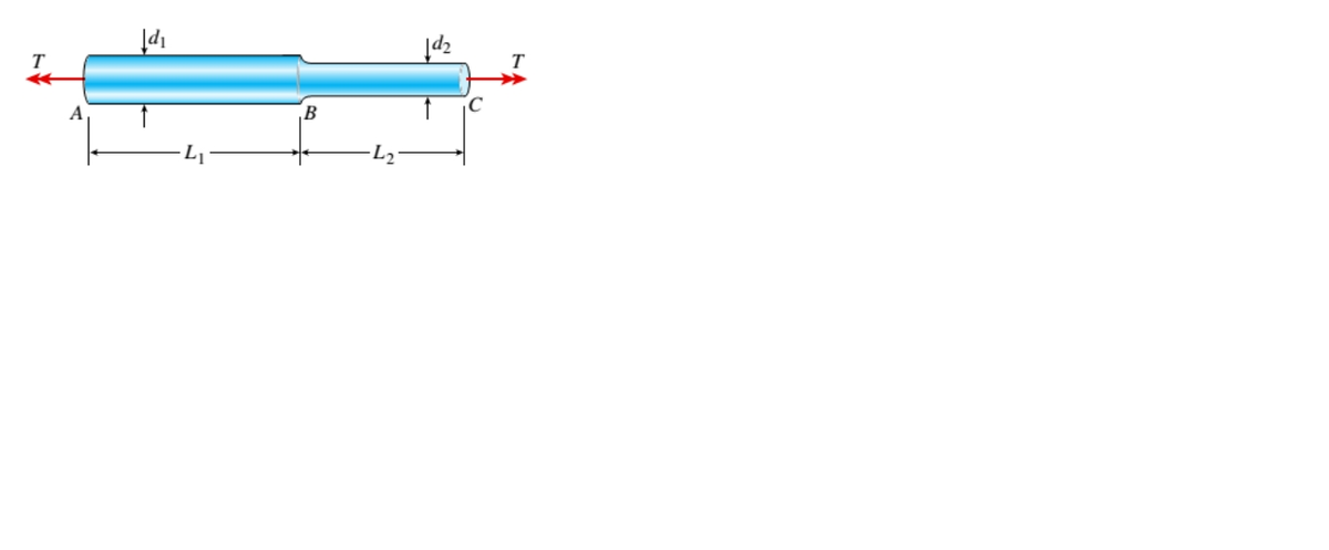
A solid, circular bar ABC consists of two segments, as shown in the figure. One segment has a diameter of d1= 56 mm and length of L1= 1.45 m; the other segment has a diameter of d2= 48 mm and length of L2= 1.2 m.
What is the allowable torque Tallowif the shear stress is not to exceed 30 M Pa and the angle of twist between the ends of the bar is not to exceed 1.25°? (Assume G = 80GPa.)

Transcribed Image Text:B
Expert Solution
This question has been solved!
Explore an expertly crafted, step-by-step solution for a thorough understanding of key concepts.

Step by stepSolved in 3 steps with 4 images

Knowledge Booster


Learn more about
Need a deep-dive on the concept behind this application? Look no further. Learn more about this topic, mechanical-engineering and related others by exploring similar questions and additional content below.Similar questions
- 3. Four pulleys are attached to the 50-mm-diameter aluminum shaft. If torques are applied to the pulleys as shown in the figure, determine the maximum shear stress in each segment and the angle of rotation of pulley D relative to pulley A. Use G = 28 GPa for aluminum. a. Tab= b. Tbc= C. Tbc= ad= 1100 N·m 800 N·m D C 900 N·m 600 N m B A 2 m3 m2 marrow_forwardTwo solid circular shafts (i.e., AB and BC) are fixed to rigid walls at point A and C, respectively. Members AB and BC are coupled together through a rigid plate at B. As shown in the figure, an external torque is applied at point B. Determine the absolute maximum shear stress developed in the whole structure AC. Both members AB and BC are made of the aluminum alloy with shear modulus G = 60 GPa. 150 mm 100 mm B 10 mm 5 kN-m Note: ignore the effect of stress concentration. 20 mmarrow_forwardI need the answer as soon as possiblearrow_forward
- Please help. This problem involves torsional stress and strain. Thank you.arrow_forwardThe shaft in Figure below consists of a 3-in. -diameter aluminum segment that is rigidly joined to a 2-in. -diameter steel segment. The ends of the shaft are attached to rigid supports, Calculate the maximum shear stress developed in each segment when the torque T= 10 kip.in is applied. Use G = 4×10⁶ psi for aluminum and G = 12×106 psi for steel. Aluminum 3-in. diameter 6 ft T Steel 2-in. diameter 3 ftarrow_forward
arrow_back_ios
arrow_forward_ios
Recommended textbooks for you
- Elements Of ElectromagneticsMechanical EngineeringISBN:9780190698614Author:Sadiku, Matthew N. O.Publisher:Oxford University Press
 Mechanics of Materials (10th Edition)Mechanical EngineeringISBN:9780134319650Author:Russell C. HibbelerPublisher:PEARSON
 Thermodynamics: An Engineering ApproachMechanical EngineeringISBN:9781259822674Author:Yunus A. Cengel Dr., Michael A. BolesPublisher:McGraw-Hill Education
  Control Systems EngineeringMechanical EngineeringISBN:9781118170519Author:Norman S. NisePublisher:WILEY
 Mechanics of Materials (MindTap Course List)Mechanical EngineeringISBN:9781337093347Author:Barry J. Goodno, James M. GerePublisher:Cengage Learning
 Engineering Mechanics: StaticsMechanical EngineeringISBN:9781118807330Author:James L. Meriam, L. G. Kraige, J. N. BoltonPublisher:WILEY
Elements Of Electromagnetics
Mechanical Engineering
ISBN:9780190698614
Author:Sadiku, Matthew N. O.
Publisher:Oxford University Press
Mechanics of Materials (10th Edition)
Mechanical Engineering
ISBN:9780134319650
Author:Russell C. Hibbeler
Publisher:PEARSON
Thermodynamics: An Engineering Approach
Mechanical Engineering
ISBN:9781259822674
Author:Yunus A. Cengel Dr., Michael A. Boles
Publisher:McGraw-Hill Education
Control Systems Engineering
Mechanical Engineering
ISBN:9781118170519
Author:Norman S. Nise
Publisher:WILEY
Mechanics of Materials (MindTap Course List)
Mechanical Engineering
ISBN:9781337093347
Author:Barry J. Goodno, James M. Gere
Publisher:Cengage Learning
Engineering Mechanics: Statics
Mechanical Engineering
ISBN:9781118807330
Author:James L. Meriam, L. G. Kraige, J. N. Bolton
Publisher:WILEY