Introductory Circuit Analysis (13th Edition)
13th Edition
ISBN: 9780133923605
Author: Robert L. Boylestad
Publisher: PEARSON
expand_more
expand_more
format_list_bulleted
Concept explainers
Question
Stop ducking the question and just answer it.
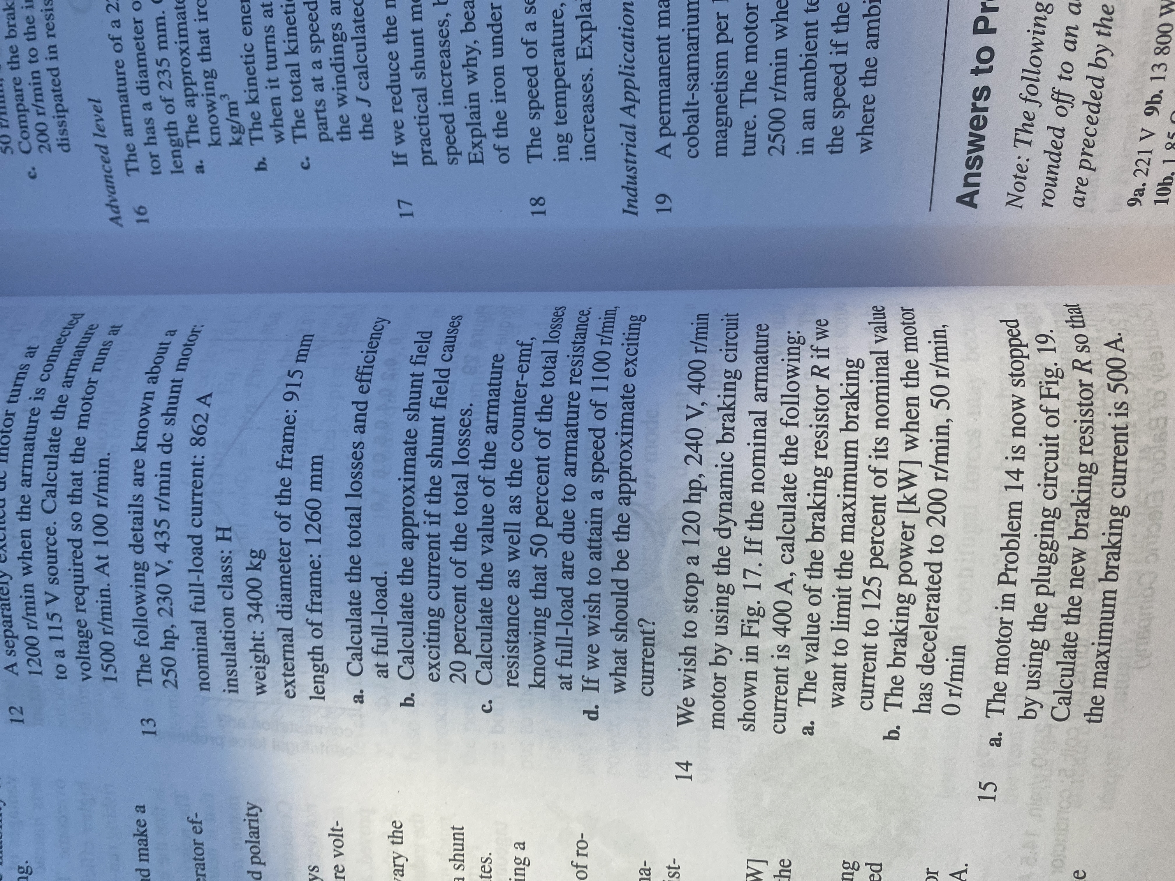
Number 14 letter a.

Transcribed Image Text:12 A separatel
otor turns at
ng.
c. Compare the brak
200 r/min to the in
voltage required
1500 r/min. At 100 r/min.
dissipated in resis
16 The armature of a 2:
tor has a diameter o
length of 235 mm. C
a. The approximate
knowing that irc
kg/m³
b. The kinetic ener
when it turns at
Advanced level
nd make a
erator ef-
insulation class: H
d polarity
weight: 3400 kg
external diameter of the frame: 915 m
c. The total kineti
parts at a speed
the windings an
the J calculated
length of frame: 1260 mm
re volt-
. Calculate the total losses and efficiency
at full-load.
ary the
exciting current if the shunt field canse
20 percent of the total losses.
c. Calculate the value of the armature
resistance as well as the counter-emf.
17 If we reduce the n
practical shunt me
speed increases, b
Explain why, bea
of the iron under
a shunt
tes.
ing a
18 The speed of a se
ing temperature,
increases. Expla
of ro-
d. If we wish to attain a speed of 1100 r/min
what should be the approximate exciting
na-
current?
Industrial Application
14 We wish to stop a 120 hp, 240 V, 400 r/min
A permanent ma
cobalt-samarium
motor by using the dynamic braking circuit
shown in Fig. 17. If the nominal armature
current is 400 A, calculate the following:
a. The value of the braking resistor R if we
want to limit the maximum braking
[M
che
magnetism per I
ture. The motor
2500 r/min whe
in an ambient te
the speed if the
where the ambi
current to 125 percent of its nominal value
pa
has decelerated to 200 r/min, 50 r/min,
0 r/min
IC
A.
15 a. The motor in Problem 14 is now stopped
Answers to Pr
Calculate the new braking resistor R so
the maximum braking current is 500 A.
Note: The following
rounded off to an a
are preceded by the
1S
9a. 221 V 9b. 13 800 W
10b. 1 85 O

Transcribed Image Text:50
Speed
+,
DIRECT-CURRENT MOTORS
110
75
dyna
R.
25
plugging
0.
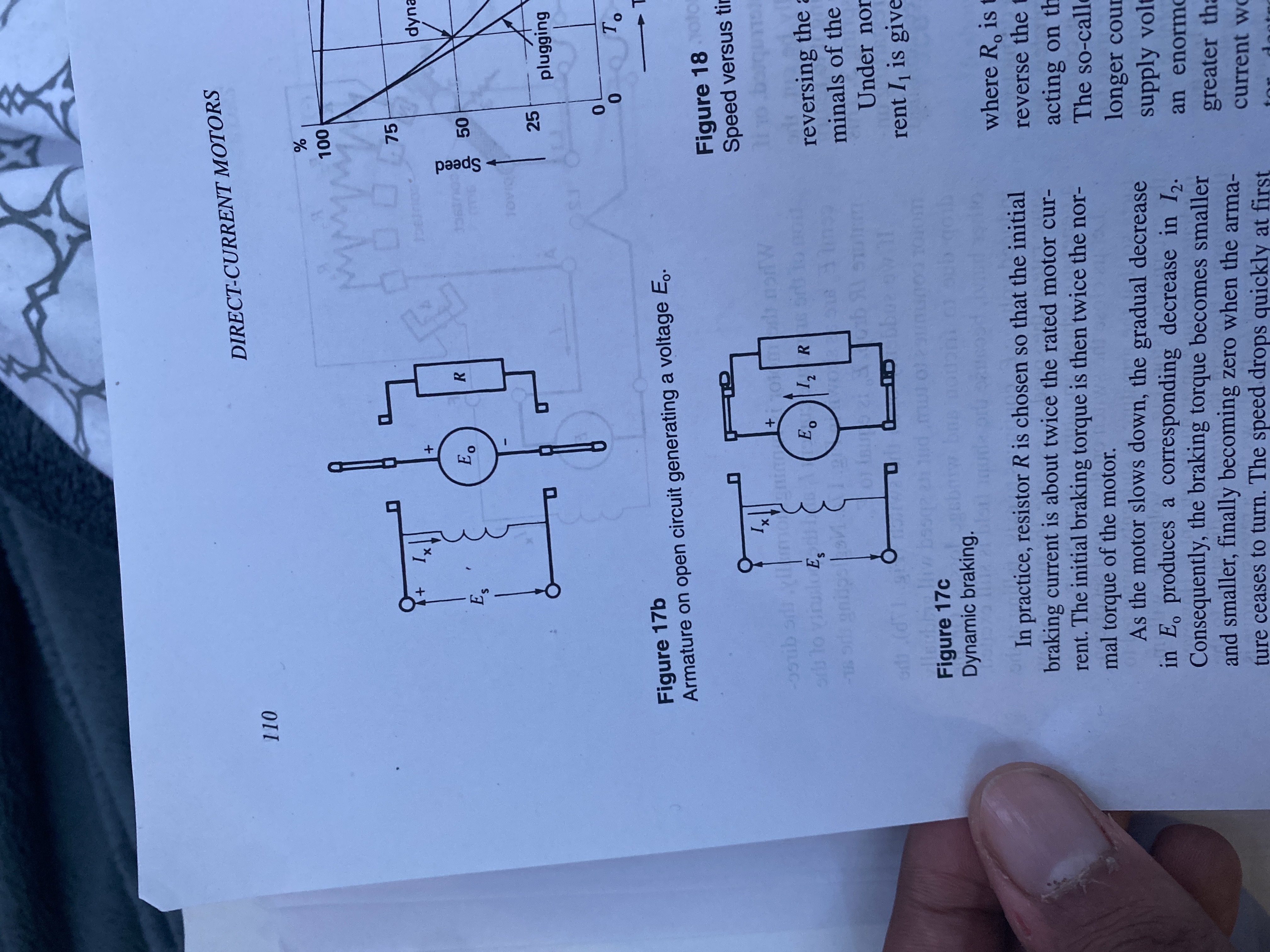
Figure 17b
Armature on open circuit generating a voltage E..
Figure 18otor
Speed versus tin
ors to vinulo E, E R
reversing the a
minals of the
L-
Under nor
41
rent I is give
Figure 17c
Dynamic braking.
where R, is t
In practice, resistor R is chosen so that the initial
braking current is about twice the rated motor cur-
rent. The initial braking torque is then twice the nor-
mal torque of the motor.
As the motor slows down, the gradual decrease
in E, produces a corresponding decrease in I,.
Consequently, the braking torque becomes smaller
and smaller, finally becoming zero when the arma-
ture ceases to turn. The speed drops quickly at first
reverse the t
acting on th
The so-calle
longer cour
supply volt
an enormo
greater tha
current wo
Expert Solution
This question has been solved!
Explore an expertly crafted, step-by-step solution for a thorough understanding of key concepts.
This is a popular solution
Trending nowThis is a popular solution!
Step by stepSolved in 2 steps with 2 images

Knowledge Booster
Learn more about
Need a deep-dive on the concept behind this application? Look no further. Learn more about this topic, electrical-engineering and related others by exploring similar questions and additional content below.Similar questions
- v Question Completion Status: Moving to another question will save this response. Quèstion 3 The value of 0.050950502 rounded to three significant digits is 0.0510 0.051 6:510 0.0509 NS bA Moving to another question will save this response. O Oarrow_forwardcan ou please answer question d?arrow_forwardQuestion No. 9 Differentiate between Gray and BCD Codes.arrow_forward
- Fill the blanks with a suitable word: 1. There are two basic system of referencing technical documents----- 2. The elements style of report can be summed up very simply-- 3. For a short report a summary should be about ----------words, and for a major research report, summary may be as 4. A network include---------, The standard components of a report are 5. and 6. The ---------- is an instrument used for sending and receiving voice messages and data? 7. Information system contains two main parts---- ----and---arrow_forwardQuestion No. 5 Perform following operations i. (11100011)2- (10101010)2 ii. 789 + 234 → (BCD Addition)arrow_forwardDesign a fritzining scheme for sign language translator glove should include breadboard, hc-05 bluetooth, adxl335, 5xflex sensors, 10k resistors and arduino nano. Please explain detailed connections i am new about arduino and breadboard connections.arrow_forward
- Do the following binary subtraction: 111000000.00111- 011000110.100 11 (Note : The problem should be solved in separate paper with steps and scanned copy should be submitted along with other answers The final answer must be entered in the boxes below. Enter only one bit in a box and fill the unused boxes if any, with zeros) Answer - Integer part = Answer - Fractional part=arrow_forwardi need the answer quicklyarrow_forwardA simple diode rectifier has 'ripples' in the output wave which makes it unsuitable as a DC source. To overcome this one can use, O a. An inductor in parallel to the load resistance O b. A capacitor in series with a the load resistance O C. An inductor in series with a the load resistance O d. A capacitor in parallel to the load resistancearrow_forward
arrow_back_ios
SEE MORE QUESTIONS
arrow_forward_ios
Recommended textbooks for you
 Introductory Circuit Analysis (13th Edition)Electrical EngineeringISBN:9780133923605Author:Robert L. BoylestadPublisher:PEARSON
 Delmar's Standard Textbook Of ElectricityElectrical EngineeringISBN:9781337900348Author:Stephen L. HermanPublisher:Cengage Learning
 Programmable Logic ControllersElectrical EngineeringISBN:9780073373843Author:Frank D. PetruzellaPublisher:McGraw-Hill Education
 Fundamentals of Electric CircuitsElectrical EngineeringISBN:9780078028229Author:Charles K Alexander, Matthew SadikuPublisher:McGraw-Hill Education
 Electric Circuits. (11th Edition)Electrical EngineeringISBN:9780134746968Author:James W. Nilsson, Susan RiedelPublisher:PEARSON
 Engineering ElectromagneticsElectrical EngineeringISBN:9780078028151Author:Hayt, William H. (william Hart), Jr, BUCK, John A.Publisher:Mcgraw-hill Education,

Introductory Circuit Analysis (13th Edition)
Electrical Engineering
ISBN:9780133923605
Author:Robert L. Boylestad
Publisher:PEARSON

Delmar's Standard Textbook Of Electricity
Electrical Engineering
ISBN:9781337900348
Author:Stephen L. Herman
Publisher:Cengage Learning

Programmable Logic Controllers
Electrical Engineering
ISBN:9780073373843
Author:Frank D. Petruzella
Publisher:McGraw-Hill Education

Fundamentals of Electric Circuits
Electrical Engineering
ISBN:9780078028229
Author:Charles K Alexander, Matthew Sadiku
Publisher:McGraw-Hill Education

Electric Circuits. (11th Edition)
Electrical Engineering
ISBN:9780134746968
Author:James W. Nilsson, Susan Riedel
Publisher:PEARSON

Engineering Electromagnetics
Electrical Engineering
ISBN:9780078028151
Author:Hayt, William H. (william Hart), Jr, BUCK, John A.
Publisher:Mcgraw-hill Education,