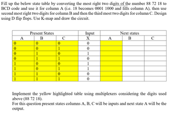
This question is from an old final exam in digital design, and I have no idea how to approach or what the correct answer is. The question is exactly as seen in the image.

Step by stepSolved in 6 steps with 14 images

how does one proceed with the second part:
"Implement the yellow highlighted table using multiplexers considering the digits used above (88 72 18). For this question present states columns A, B, C will be inputs and next state A will be the output."
Many thanks for your valuable help.
how does one proceed with the second part:
"Implement the yellow highlighted table using multiplexers considering the digits used above (88 72 18). For this question present states columns A, B, C will be inputs and next state A will be the output."
Many thanks for your valuable help.
- Can you help me with this homework problem? Constant voltage drop is Vd=0.7 What is the output volts of V? What is the current I going through the resistor? What is the diode current Id2? What is the diode current Id1? What are the states of two diodes D1 and D2?arrow_forwardis one of the best circuits to interface an analog input and digital circuit Your answerarrow_forwardPlease try please answer in typing format Please answer in typing format solution please only typingarrow_forward
- Please, see attached. Answer item number 2 and 3 only. Thank you very much!arrow_forwardBased on electric circuit shown in Figure 2. Determine whether the LED 1 and LED 2 is “ON" or "OFF" for V1 = 2V and V1 = 3.5V if for both LEDS are silicon LED. Explain the answer given. V1 OUT R1 OPAMP 100kN V2 LED 1 LED 2 4Vdc R2 500kn Figure 2: Op-Amp circuit with LEDarrow_forwardQuestion #7 Find the voltage V at the junction of the diodes (marked as red). Assume all the diodes are ideal. 7V 1 k2 D1 1 k2 D4 Vo 1 k2 6V D2 9v D3 1 k2 -6V (a) 4V (b) 0V (c) 2V (d) 1V (e) -4V (f) -2V (g) -2.5Varrow_forward
- V. Match the image with the setting Match the image with the correct digital-multimeter setting. Your setting choices are "resistance", "AC voltage", "DC voltage", "milli-ammeter", "ammeter" and "incorrect configuration." Write down the correct label below each image. mA mA (2 mA 88.88 (88.88 mA V~ A COM VO || COM VO (88.88) mA mA A COM V2 mA 88.88 52 O mA A COM να mA mA mA 88.88 53 COM VO 88.88 mA A COM ναarrow_forwardWhat did you observe on the output waveform (PR2) compare to the input waveform (PR1)? What type of clipper does circuit 1 depicts? Explain your answerarrow_forwardThis multiple choice questions from electronics lab,please solve all i think it's easy for you and good luck in your life.arrow_forward
- ii. The controlled single-phase rectifier full-wave bridge rectifier of Figure ii has an RL load with R = 252 and L = 50mH. The source is 240 V rms at 60 Hz. Determine 15° and a = 750 the average load current for a = v, (or) = Vm sin(or) Figure 2: For part (c) iiarrow_forward+12V D7 D8 R3 Vo = ? 2.2k2 Determine: a. State of D7 if D7 is Si diode b. State of D8 if D8 is Ge diode c. Output voltage Vo +arrow_forwardAnalog Meter Readingarrow_forward
 Introductory Circuit Analysis (13th Edition)Electrical EngineeringISBN:9780133923605Author:Robert L. BoylestadPublisher:PEARSON
 Delmar's Standard Textbook Of ElectricityElectrical EngineeringISBN:9781337900348Author:Stephen L. HermanPublisher:Cengage Learning
 Programmable Logic ControllersElectrical EngineeringISBN:9780073373843Author:Frank D. PetruzellaPublisher:McGraw-Hill Education
 Fundamentals of Electric CircuitsElectrical EngineeringISBN:9780078028229Author:Charles K Alexander, Matthew SadikuPublisher:McGraw-Hill Education
 Electric Circuits. (11th Edition)Electrical EngineeringISBN:9780134746968Author:James W. Nilsson, Susan RiedelPublisher:PEARSON
 Engineering ElectromagneticsElectrical EngineeringISBN:9780078028151Author:Hayt, William H. (william Hart), Jr, BUCK, John A.Publisher:Mcgraw-hill Education,


