What are Analog to Digital converters?
The analog-to-digital converter (ADC) allows circuits controlled by microprocessors, Arduinos, Raspberry Pi, and various reasonable digital circuits to be connected to the real world. In the real world, analog signals have a continuous stream of information from a variety of sources and sensors capable of measuring sound, light, temperature, or movement, in addition to the many digital systems that interact with their environment by measuring analog signals from those transducers.
Principle of Analog to Digital converters
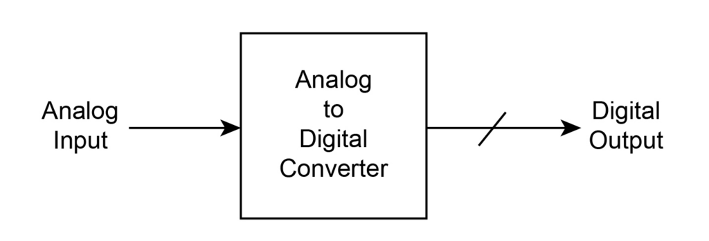
The analog-to-digital converter simultaneously obtains the analog voltage summary and generates a digital output code representing the analog voltage. The binary number or number of bits used to represent the value of this analog voltage depends on the configuration of the A/D converter.
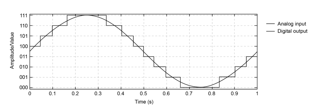
Although analog signals may be continuous and provide an infinite number of different electrical values, digital circuits however perform with a binary signal with only two different states, logic “1” (high) or logic “0” (low). It is therefore necessary to have an electronic circuit that could switch between two different domains for constantly switching analog signals and different digital signals, and that is where the Analog-to-digital (A/D) converters fit.
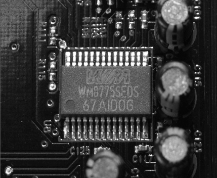
CC0 1.0 Universal Public Domain Dedication | https://commons.wikimedia.org | Andrzej Barabasz
Types of Analog-to-Digital converters
There are different types of analog to digital converters:
- Flash ADC
- Pipelined ADC
- Sigma Delta ADC
- Successive Approximation ADC
Flash ADC
Compared with all other ADC , the performance of flash ADC is much faster. Therefore, flash ADC is used in applications that require high speed and high bandwidth. It is also known as Parallel ADC. Use flash-type ADC for low-bit resolution applications, i.e. 8-bit accuracy measurement. These are not suitable to measure more than 8 bits. Applications that require more bandwidth use flash ADC.
Pipeline ADC
The pipeline analog-to-digital converter design uses two or more low-resolution flash ADC. The architecture is divided into multiple parts, and each part contains a sample-and-hold circuit. This sample circuit is an analog signal and holds the sample value for a short period. This signal is provided by lfash ADC for binary output.
Sigma Delta ADC
One of the most futuristic technology for the ADC is the sigma-delta conversion technique and this is denoted by the Greek notation as Σ-Δ, here the delta denotes the change and the sigma denotes the summation. In this converter the input voltage is given through the integrator that produce an output as form of variable voltage such that the magnitude of the output corresponds to a slope. This voltage is then compared to the ground potential by the comparator. Here, the comparator is the single bit ADC that produce single bit high output and this output depend on the input provided by the integrator whether negative or positive. The output of the comparator is given to the D flip flop and then given to the integrator to some other channel.
Example: ADS1258 from Texas instruments.
Successive Approximation ADC
The successive approximation ADC is the type of the converter that convert the analog input signal of continuous nature to the discrete output. This conversion process includes a binary search including the process of quantization. The circuit includes the sample and hold circuit followed by the voltage comparator. The circuit is used to converter the analog input voltage to a digital code with the aid of register sub circuit.
Block diagram of Analog-to-Digital converters
The ADC block diagram is shown below which includes sample and hold circuit and embedded conversion sets.
The converter converts the continuous signals to sampled discrete signals. The signal is first sampled at a fixed time interval for the systems requirement, then the sample is hold unit the next sample is obtained. The signal is then quantized to obtain the discrete signal from the continuous one. At last the encoder is used to obtain the coded form of the signal.
Operation of Analog-to-Digital converters
The process of taking an analog electric signal and converting it to the same digital signal can be completed in many different ways, and although there are many variations of analog-to-digital on-chips such as the ADC08xx series available to different manufacturers, it is possible to build an easy-to-use ADC component.
One simple and easy way is to use standard encoding, also known as flash converters, simultaneous, or multiple scanners where scanners are used to detect different levels of power and extract their switches from the embedded.
The similarities of the "Flash" A/D converters use a series of parallel but equally comparing comparisons and an electronic reference generated using a series of precise shortcut networks to produce the same output code for n-bit correction.
The advantage of parallel or flash converters is that they are easy to build and do not need any clocks, because the analog voltage is simultaneously applied to the comparator input which is compared to the reference voltage.
Uses of Analog-to-Digital converters
There are a few Analog to Digital Converter (adcs) applications listed below:
- Used in audio/video equipment.
- Used in cell phones.
- They're utilized in digital Multimeters, PLCs (Programming Logic Controls).
- They're used within the processing of RADAR, digital oscilloscopes.
- They're widely utilized in CMOS photograph sensors for mobile applications.
- They're utilized in medical Instrumentation and medical imaging.
Common Mistakes
Remember that, circuit complexity increases with the use of Comparators in Flash ADCs. Flash ADCs are expensive. Converting non-temporary signals using Pipeline ADCs can be difficult as they often work overtime.
Context and Applications
In each of the expert exams for undergraduate and graduate publications, this topic is huge and is mainly used for:
- Bachelor of Technology in the Electrical and Electronic Department
- Bachelor of Science in Physics
- Master of Science in Physics
Related Concepts
Digital to Analog converters (DAC)
Practice Problems
Q1 Which of the following is the integrating type analog to the digital converter?
(a) Dual slope ADC
(b) Tracking converter
(c) Flash-type converter
(d) Counter type converter
Correct option- (a)
Explanation- Dual-slope ADC is the integrating type analog to digital converter.
Q2 Drawback of counter type A/D converter is __________.
(a) more complex
(b) high conversion time
(c) low speed
(d) counter clears automatically
Correct option- (c)
Explanation- In the case of the ADC converter counter frequency, it is kept low enough to provide sufficient time for the DAC to stabilize and the response ratio. Therefore, low speed is a major drawback.
Q3 Condition error occurs in the servo tracking A/D Converter due to _______.
(a) slow change input
(b) rapid change
(c) both
(d) none of these
Correct option- (b)
Explanation- As long as the analog input changes slightly, the A / D tracking converter will be within one LSB of the fixed value. If the input changes quickly, the A / D tracker converter cannot keep up with the change and an error occurs.
Q4 The advantage of using flash type A/D converter is _____.
(a) high-speed conversion
(b) low-speed conversion
(c) both
(d) none of these
Correct option-(a)
Explanation- Compared with all other ADC , the performance of flash ADC is much faster. Therefore, flash ADC is used in applications that require high speed and high bandwidth.
Q5 The number of comparators required for flash type A/D converter is _____.
(a) 2n
(b) 2n -1
(c) 2n +1
(d) none of these
Correct option- (b)
Explanation- The number of comparitor required for flash type A/D converter is 2n -1. Example - 2 -bit ADC requires three compartments, 3 -bit ADC requires seven components, and 4 -bit ADC requires fifteen components.
Want more help with your electrical engineering homework?
*Response times may vary by subject and question complexity. Median response time is 34 minutes for paid subscribers and may be longer for promotional offers.
Search. Solve. Succeed!
Study smarter access to millions of step-by step textbook solutions, our Q&A library, and AI powered Math Solver. Plus, you get 30 questions to ask an expert each month.
Analog to Digital Converters Homework Questions from Fellow Students
Browse our recently answered Analog to Digital Converters homework questions.
Search. Solve. Succeed!
Study smarter access to millions of step-by step textbook solutions, our Q&A library, and AI powered Math Solver. Plus, you get 30 questions to ask an expert each month.