
Introductory Circuit Analysis (13th Edition)
13th Edition
ISBN: 9780133923605
Author: Robert L. Boylestad
Publisher: PEARSON
expand_more
expand_more
format_list_bulleted
Related questions
Question
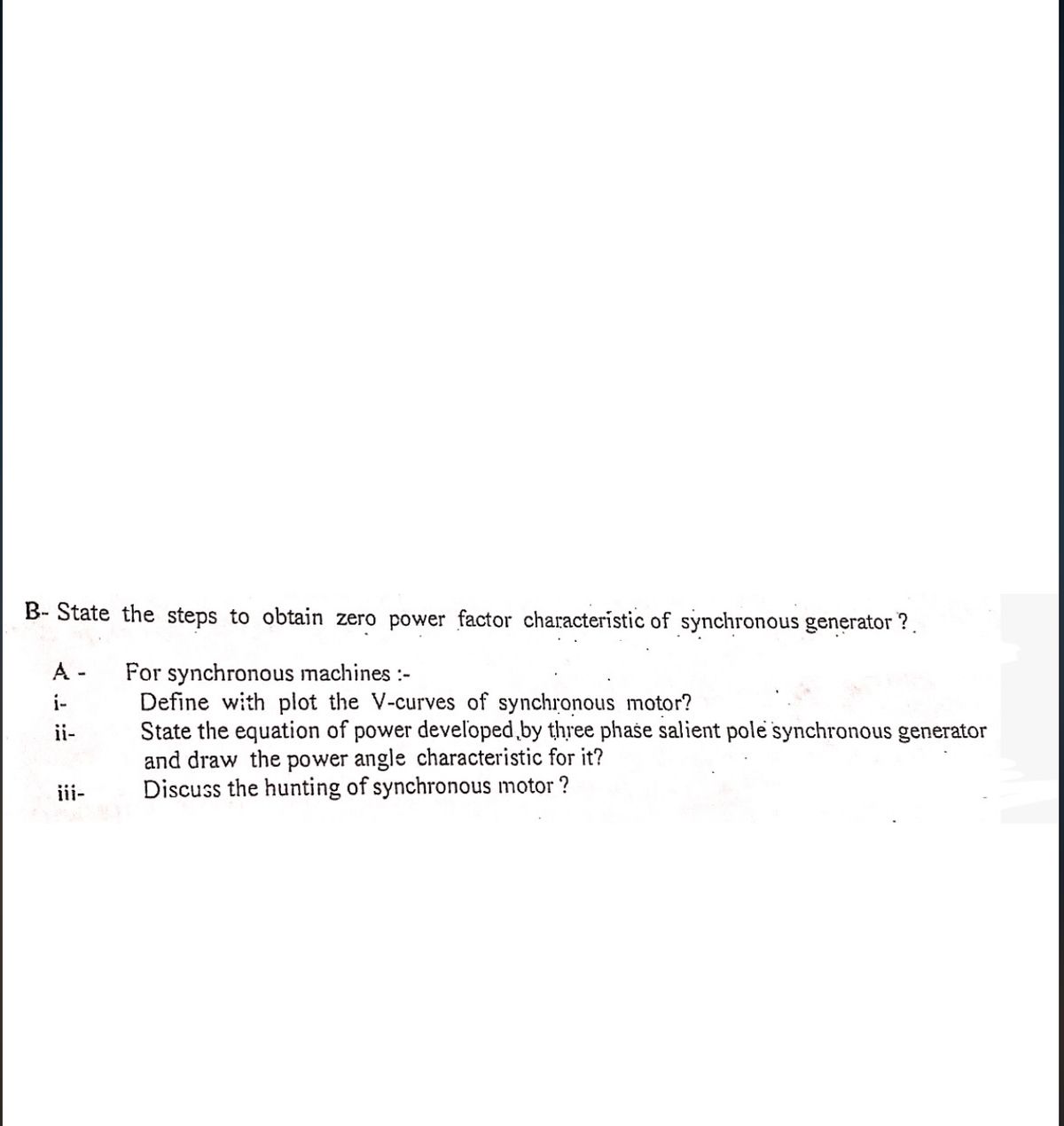

Transcribed Image Text:B-State the steps to obtain zero power factor characteristic of synchronous generator?
A-
i-
ii-
iii-
For synchronous machines :-
Define with plot the V-curves of synchronous motor?
State the equation of power developed by three phase salient pole synchronous generator
and draw the power angle characteristic for it?
Discuss the hunting of synchronous motor?
Expert Solution
This question has been solved!
Explore an expertly crafted, step-by-step solution for a thorough understanding of key concepts.

Step by stepSolved in 2 steps

Knowledge Booster

Similar questions
- Explain the conditions for parallel operation of synchronous generators. A three phase, wye connected, synchronous generator is rated 150 MW, 0.85 lagging power factor, 12.6 kV, 60 Hz, and 1800 rpm. Each winding has an armature resistance of 0.05Q and a synchronous reactance of 0.6Q. Draw the phasor diagram with values, show torque angle and determine the induced voltage for the condition of rated load.arrow_forwardL-1). How would it be possible to reverse the direction of rotation of a 3-phase synchronous motor? a) reverse the polarity of the DC field excitation b) interchanging any two of the incoming supply lines c) interchanging all three of the supply lines d) none of the above L-2). The amortisseur winding of a 3-phase, synchronous motor is the.....a) squirrel-cage winding on the rotor used to start the motor b) wire wound winding on the rotor to be connected to the external DC supply by way of slip rings and brushes c) either "a" or "b" d) neither "a" nor "b" L-3). Is it ok to have the DC voltage supply connected to the rotor of a 3-phase synchronous motor while starting? a) yes b) noarrow_forwardWhat are the active components of three-phase Induction Motor? b) Derive an expression for the frequency in the rotor circuit of three-phase IM? c) Draw with details the approximate per phase equivalent circuit of three-phase IM? d) Why the iron loss in rotor of an induction motor is negligible?arrow_forward
- 4. For a general DC generator, we aim to achieve constant output voltage at different rotating speeds. (1) List two factors influencing the output voltage for a given DC generator. (2) How does the change of the load (assuming the load is the current flowing though the resistor) will impact on the generated voltage for (a) separately excited DC generator, (b) Shunt DC generator, and (c) cumulative compound DC generator?arrow_forwardPlease solve this problem step by step and illustrate your answer properly. Write your answer in a piece of paper please. Box the final answer.arrow_forward2.A 10-MVA 4.6-kV 60-Hz 6-pole three phase synchronous generator has armature resistance of 2 ohms and synchronous reactance of 6 ohms. It is operated at rated frequency to supply rated load at rated voltage at a power factor of 0.9 lagging. Assume mechanical losses are negligible. a.Determine the magnitude of the line-to-line excitation voltage. b.Determine the input power for the generator, in MW. (Please compute in W or kW before converting to MW)arrow_forward
- A three-phase, 1 MVA, 2.3 kV, 60 Hz, star-connected, salient pole synchronous generator has the d- and q-axis synchronous reactances are 1.1 and 0.8 Q respectively. Its armature has a resistance of 0.15 §. The machine is operating at full load at a power factor of 0.8 lagging. Determine the excitation voltage Ę and draw the generator phasor diagram using actual values.arrow_forwardA 300 KW and 600 V Long shunt compound DC generator has shunt field resistance = 100 2 armature resistance = 0.05 Q series field resistance = 0.02 Q commutating field winding resistance = 0.015 N connected in series with armature winding and diverter resistance = 0.03 N connected in parallel with commutating field. When the generator is delivering half full load, calculate power generated by the armature.arrow_forward3arrow_forward
- With the aid of diagrams describe the basic topology of a wound field 3 phase synchronous generator and outline the relationship between the excitation voltage and rotor current. Q2 (a) (b) Outline with the aid of a suitable diagram the necessary power conversion stages required to interface a small permanent magnet (PM) generator to a stand alone DC system. A star connected 3 phase wound field synchronous generator with a synchronous reactance of 20 N is connected to a 6.6 kV (phase voltage) grid and supplies 1.5 MW at 0.95 lagging power factor at its terminals. Calculate the phase current and resultant voltage across the synchronous reactance (Vxs), and from a scaled phasor diagram graphically determine the required excitation voltage (Eph) and load angle (8). (c) The load is now increased to 3 MW with the Excitation Voltage kept constant. Using the phasor diagram drawn in part (c) graphically determine the resultant phase current, power factor and load angle. (d)arrow_forwardhele Ish 0.05 50 A To R 30 Aarrow_forwardSingle phase induction motor performance characteristics 6. Explain double revolving field theory.arrow_forward
arrow_back_ios
SEE MORE QUESTIONS
arrow_forward_ios
Recommended textbooks for you
- Introductory Circuit Analysis (13th Edition)Electrical EngineeringISBN:9780133923605Author:Robert L. BoylestadPublisher:PEARSON
 Delmar's Standard Textbook Of ElectricityElectrical EngineeringISBN:9781337900348Author:Stephen L. HermanPublisher:Cengage Learning
 Programmable Logic ControllersElectrical EngineeringISBN:9780073373843Author:Frank D. PetruzellaPublisher:McGraw-Hill Education
  Fundamentals of Electric CircuitsElectrical EngineeringISBN:9780078028229Author:Charles K Alexander, Matthew SadikuPublisher:McGraw-Hill Education
 Electric Circuits. (11th Edition)Electrical EngineeringISBN:9780134746968Author:James W. Nilsson, Susan RiedelPublisher:PEARSON
 Engineering ElectromagneticsElectrical EngineeringISBN:9780078028151Author:Hayt, William H. (william Hart), Jr, BUCK, John A.Publisher:Mcgraw-hill Education,
Introductory Circuit Analysis (13th Edition)
Electrical Engineering
ISBN:9780133923605
Author:Robert L. Boylestad
Publisher:PEARSON
Delmar's Standard Textbook Of Electricity
Electrical Engineering
ISBN:9781337900348
Author:Stephen L. Herman
Publisher:Cengage Learning
Programmable Logic Controllers
Electrical Engineering
ISBN:9780073373843
Author:Frank D. Petruzella
Publisher:McGraw-Hill Education
Fundamentals of Electric Circuits
Electrical Engineering
ISBN:9780078028229
Author:Charles K Alexander, Matthew Sadiku
Publisher:McGraw-Hill Education
Electric Circuits. (11th Edition)
Electrical Engineering
ISBN:9780134746968
Author:James W. Nilsson, Susan Riedel
Publisher:PEARSON
Engineering Electromagnetics
Electrical Engineering
ISBN:9780078028151
Author:Hayt, William H. (william Hart), Jr, BUCK, John A.
Publisher:Mcgraw-hill Education,