Introductory Circuit Analysis (13th Edition)
13th Edition
ISBN: 9780133923605
Author: Robert L. Boylestad
Publisher: PEARSON
expand_more
expand_more
format_list_bulleted
Concept explainers
Question

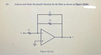
Transcribed Image Text:(b)
Analyse and obtain the transfer function for the filter as shown in Figure Q2(b).
R₁
VW
HH
R₂
W
Figure Q2 (b)
Expert Solution
This question has been solved!
Explore an expertly crafted, step-by-step solution for a thorough understanding of key concepts.
Step by stepSolved in 2 steps with 1 images

Knowledge Booster
Learn more about
Need a deep-dive on the concept behind this application? Look no further. Learn more about this topic, electrical-engineering and related others by exploring similar questions and additional content below.Similar questions
- 4. Part A: Filters 1. 3. Assignment#5 Refer to Electronic Devices, Floyd chapters 15, 16 and 17 2. The term pole in filter terminology refers to (a) a high-gain op-amp (c) a single RC circuit (b) one complete active filter (d) the feedback circuit A band-pass response has (a) two critical frequencies (c) a flat curve in the passband (b) one critical frequency (d) a wide bandwidth When a low-pass and a high-pass filter are cascaded to get a band-pass filter, the critical frequency of the low-pass filter must be (a) equal to the critical frequency of the high-pass filter (b) less than the critical frequency of the high-pass filter (c) greater than the critical frequency of the high-pass filter When the gain of a filter is minimum at its center frequency, it is (a) a band-pass filter (b) a band-stop filter (c) a notch filter (d) answers (b) and (c)arrow_forwardFor the circuit shown below, assuming Lambda = 0, the feedback gain k is: Rpl R₁ 11₁ O b. k=-1 Select one: Oa. None of these gm2.RD d. k=- R2 Ock=- R1 R2 R₂ Rp1 Q₂ R1/(1/gm1) RI/(1/gml)+182 -OV Rarrow_forward.Sallen-Key is one of the most common filter configurations for designing first- order (1st-order) and second-order (2nd-order) filters, Figure 2 shows Sallen-Key High Pass Filter. Determine the transfer function of Vout/Vin. Let C₁ = C₂ = 100nF, R₁ R₂ = 8kN. = Vin C₁ C₂ R₂ R₁ op amp Figure 2 Voutarrow_forward
- The figure below plots the frequency response of a multi-pole amplifier. A feedback system employing this amplifier with K = 1 will be: Bode Diagram Magnitude (dB) Phase (deg) 0 -20 40 -60 -80 -100 -90 -135 -180 -225 10-1 10° Frequency (rad/s) Select one: O a. stable because WGX wpx 10¹ 10²arrow_forwardX=2 Y=8arrow_forwardNeed help steps would be helpful please and thank you!arrow_forward
- (b) Block diagram of a system with unity feedback is illustrated as R(s) Y(s) K G(s) Figure Q3(b) and the transfer function is given as 50000 G(s) = s² + 150s + 5000 From the given block diagram and transfer function, sketch an approximate magnitude and phase of Bode Plot. Choose any value of K that you might think will simplify your sketching. There is no requirement of K value in this sketching process. The selection of Kis only necessary if you have a particular design requirement.arrow_forward3. Active Analog Filter Topologies You already know from our class discussions that Circuit 1 is an active analog Low-Pass Filter For each of the remaining three circuits, state whether the circuit will function as a low-pass or high-pass filter. Each of your answers must be accompanied by a brief explanation and justification incorporating the frequency dependent characteristics of the reactive circuit elements. That is you should look at the asymptotic impedance of the L and C if the input signal the frequency is very low or very high. Sketch the expected Bode plot for 20 log(Vo/Vs) as a function of log (f) labeling the corner frequencies. No equations are required! R2 R2 R2 R2 R1 R1 R1 Vs Vs o W- Vs Vs Vo Vo Vo Vo Circuit 1 Citcuit 2 Circuit 3 Circuit 4arrow_forwardQ3: Design a Low-Pass Active Filter to produce the response illustrated in Figure 2. What would you suggest to make the roll-off rate rises up to -160 dB? Gain (dB) -3 -120 100 MHz Figure 2 -120 dB/decadearrow_forward
- help with all parts of the question thanksarrow_forwardHelp on this questionarrow_forwardAssume the op-amps are ideal for the filters that follow.Now; Determine the transfer functions, T(s). ii. Plot the magnitude and phase responses of each filter if R1 = 10kΩ, R2 = 100kΩ, C1 = 1μF, C2 = 0.1μF, L1 = 1nH, and L 2 = 1μH.arrow_forward
arrow_back_ios
arrow_forward_ios
Recommended textbooks for you
 Introductory Circuit Analysis (13th Edition)Electrical EngineeringISBN:9780133923605Author:Robert L. BoylestadPublisher:PEARSON
 Delmar's Standard Textbook Of ElectricityElectrical EngineeringISBN:9781337900348Author:Stephen L. HermanPublisher:Cengage Learning
 Programmable Logic ControllersElectrical EngineeringISBN:9780073373843Author:Frank D. PetruzellaPublisher:McGraw-Hill Education
 Fundamentals of Electric CircuitsElectrical EngineeringISBN:9780078028229Author:Charles K Alexander, Matthew SadikuPublisher:McGraw-Hill Education
 Electric Circuits. (11th Edition)Electrical EngineeringISBN:9780134746968Author:James W. Nilsson, Susan RiedelPublisher:PEARSON
 Engineering ElectromagneticsElectrical EngineeringISBN:9780078028151Author:Hayt, William H. (william Hart), Jr, BUCK, John A.Publisher:Mcgraw-hill Education,

Introductory Circuit Analysis (13th Edition)
Electrical Engineering
ISBN:9780133923605
Author:Robert L. Boylestad
Publisher:PEARSON

Delmar's Standard Textbook Of Electricity
Electrical Engineering
ISBN:9781337900348
Author:Stephen L. Herman
Publisher:Cengage Learning

Programmable Logic Controllers
Electrical Engineering
ISBN:9780073373843
Author:Frank D. Petruzella
Publisher:McGraw-Hill Education

Fundamentals of Electric Circuits
Electrical Engineering
ISBN:9780078028229
Author:Charles K Alexander, Matthew Sadiku
Publisher:McGraw-Hill Education

Electric Circuits. (11th Edition)
Electrical Engineering
ISBN:9780134746968
Author:James W. Nilsson, Susan Riedel
Publisher:PEARSON

Engineering Electromagnetics
Electrical Engineering
ISBN:9780078028151
Author:Hayt, William H. (william Hart), Jr, BUCK, John A.
Publisher:Mcgraw-hill Education,