
Structural Analysis
6th Edition
ISBN: 9781337630931
Author: KASSIMALI, Aslam.
Publisher: Cengage,
expand_more
expand_more
format_list_bulleted
Related questions
Concept explainers
Question
thumb_up100%
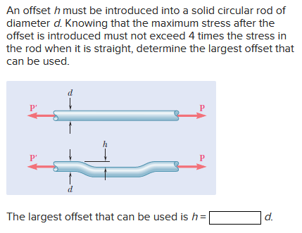

Transcribed Image Text:An offset \( h \) must be introduced into a solid circular rod of diameter \( d \). Knowing that the maximum stress after the offset is introduced must not exceed 4 times the stress in the rod when it is straight, determine the largest offset that can be used.
**Diagram Explanation:**
Two diagrams of the rod are shown:
1. **Top Diagram:**
- A straight rod with diameter \( d \).
- Two horizontal arrows labeled \( P' \) indicate the forces acting on the rod.
2. **Bottom Diagram:**
- The same rod with an offset \( h \) introduced.
- The rod still has a diameter \( d \).
- Two horizontal arrows labeled \( P \) indicate the forces acting on the offset rod.
- The height of the offset \( h \) is marked perpendicular to the rod's length.
The largest offset that can be used is \( h = \_\_\_\_\_ \, d \).
Expert Solution
This question has been solved!
Explore an expertly crafted, step-by-step solution for a thorough understanding of key concepts.

This is a popular solution

Trending nowThis is a popular solution!

Step by stepSolved in 4 steps with 5 images

Knowledge Booster


Learn more about
Need a deep-dive on the concept behind this application? Look no further. Learn more about this topic, civil-engineering and related others by exploring similar questions and additional content below.Similar questions
- 8. The cross section of the machine part is a square, 5 mm on a side. If the maximum stress at section m-n is limited to 150 MPa, determine the largest allowable value of the eccentricity e. 250 N 250 Narrow_forwardA bar of a uniform cross-section is rigidly fixed at one end and loaded by an off-centre tensile point load F = 1.5 kN at the other end, see Fig. Q1a. The Figure Q1b presents the view of the beam from the free end where the point of application of the load F is indicated as A. The allowable stress [0]=234 MPa The geometrical parameters are given as follow h 18 mm, b=37 mm N y b Figure Q1a Figure Q1b h F Xarrow_forward3. For the given state of stress, determine the principal planes, the principal stresses, the max shear stress. You must use Mohr's Circle. 20 MPa 32 MPa 55 MPaarrow_forward
- A 180-mm length of 30 x 40 mm solid rectangular bar is loaded as shown in the diagram. The right end of the tube is fixed to a rigid frame while the left end is free. (a) Draw the stress element for point B at the top center of the bar (right end) and label the stress vectors acting on the element, including the stress magnitudes. (b) Draw the stress element for point C at the middle of the front face of the bar (right end) and label the stress vectors acting on the element, including stress magnitudesarrow_forwardA high-strength steel [E = 188 GPa] tube having an outside diameter of 67 mm and a wall thickness of 4.1 mm is bent into a circular curve having a 42-m radius of curvature. Determine the maximum magnitude of the bending stress max developed in the tube. Answer: Omax = i MPa.arrow_forwardIf the block is subjected to the centrally applied force of 600kN, determine the average normal stress in the material. Show the stress acting on a differential volume element of the materialarrow_forward
arrow_back_ios
arrow_forward_ios
Recommended textbooks for you
 Structural Analysis (10th Edition)Civil EngineeringISBN:9780134610672Author:Russell C. HibbelerPublisher:PEARSON
 Principles of Foundation Engineering (MindTap Cou...Civil EngineeringISBN:9781337705028Author:Braja M. Das, Nagaratnam SivakuganPublisher:Cengage Learning
 Fundamentals of Structural AnalysisCivil EngineeringISBN:9780073398006Author:Kenneth M. Leet Emeritus, Chia-Ming Uang, Joel LanningPublisher:McGraw-Hill Education
 Traffic and Highway EngineeringCivil EngineeringISBN:9781305156241Author:Garber, Nicholas J.Publisher:Cengage Learning
Structural Analysis (10th Edition)
Civil Engineering
ISBN:9780134610672
Author:Russell C. Hibbeler
Publisher:PEARSON
Principles of Foundation Engineering (MindTap Cou...
Civil Engineering
ISBN:9781337705028
Author:Braja M. Das, Nagaratnam Sivakugan
Publisher:Cengage Learning
Fundamentals of Structural Analysis
Civil Engineering
ISBN:9780073398006
Author:Kenneth M. Leet Emeritus, Chia-Ming Uang, Joel Lanning
Publisher:McGraw-Hill Education
Traffic and Highway Engineering
Civil Engineering
ISBN:9781305156241
Author:Garber, Nicholas J.
Publisher:Cengage Learning