Structural Analysis
6th Edition
ISBN: 9781337630931
Author: KASSIMALI, Aslam.
Publisher: Cengage,
expand_more
expand_more
format_list_bulleted
Concept explainers
Question
thumb_up100%

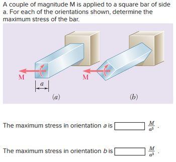
Transcribed Image Text:A couple of magnitude M is applied to a square bar of side
a. For each of the orientations shown, determine the
maximum stress of the bar.
M
|ª|
(a)
M
The maximum stress in orientation a is
The maximum stress in orientation bis
(b)
M
a³
M
Expert Solution
This question has been solved!
Explore an expertly crafted, step-by-step solution for a thorough understanding of key concepts.
This is a popular solution
Trending nowThis is a popular solution!
Step by stepSolved in 4 steps with 4 images

Knowledge Booster
Learn more about
Need a deep-dive on the concept behind this application? Look no further. Learn more about this topic, civil-engineering and related others by exploring similar questions and additional content below.Similar questions
- The split ring shown has an inner radius ₁ = 0.8 in. and a circular cross section of diameter d= 0.6 in. Knowing that each of the 100-lb forces Pis applied at the centroid of the cross section, determine the stress at point A and at point B. P B The stress at point A is The stress at point B is P ksi. ksi.arrow_forwardThe state of stress at a point is shown on the element. Enter your answers numerically separated by commas. ΥΠ ΑΣφ vec max min = ksi Submit Request Answer Figure Part B Determine the absolute maximum shear stress. ΑΣφ ve 2.5 ksi ksi Fabs mar= 4 ksi Submit Request Answer 5 ksi Provide Feedback 圓arrow_forwardA bar of a uniform cross-section is rigidly fixed at one end and loaded by an off-centre tensile point load F = 1.5 kN at the other end, see Fig. Q1a. The Figure Q1b presents the view of the beam from the free end where the point of application of the load F is indicated as A. The allowable stress [0]=234 MPa The geometrical parameters are given as follow h 18 mm, b=37 mm N y b Figure Q1a Figure Q1b h F Xarrow_forward
- The solid steel rod (1) shown in the figure has an allowable shear stress of 18 ksi. The brass tube (2) has an allowable shear stress of 6 ksi. The outside diameter of the tube is D2 = 1.50 in., and its wall thickness is t2 = 0.125 in. The tube is attached to a fixed plate at C, and both the rod and the tube are welded to a rigid end plate at B. Calculate (a) the largest torque T that can be applied at the upper end of the steel rod if the allowable shear stress in tube (2) is not to be exceeded. (b) the corresponding minimum diameter d1 required for steel rod (1). Rod (1) Tube (2) B D₂ IT -d₁ Fixed plate End platearrow_forwardThe d = 16-mm-diameter solid rod passes through a D = 21-mm-diameter hole in the support plate. When a load P is applied to the rod, the rod head rests on the support plate. The support plate has a thickness of b = 11 mm. The rod head has a diameter of a = 32 mm, and the head has a thickness of t = 10 mm. The shear stress in the rod head cannot exceed 130 MPa, the punching shear stress in the support plate cannot exceed 90 MPa, and the bearing stress between the rod head and the support plate cannot exceed 145 MPa. Determine the maximum value of Pmax that can be supported by the structure. P Support Plate Rod Answer: Pmax i Hole diameter D Head KNarrow_forwardConsider the state of plane stress shown. (Hint: Consider both in-plane and out-of-plane shearing stresses.) 7 ksi Determine the maximum shearing stress when ox- 18 ksi and ay = 8 ksl. The maximum shearing stress is ksi.arrow_forward
arrow_back_ios
arrow_forward_ios
Recommended textbooks for you

 Structural Analysis (10th Edition)Civil EngineeringISBN:9780134610672Author:Russell C. HibbelerPublisher:PEARSON
 Principles of Foundation Engineering (MindTap Cou...Civil EngineeringISBN:9781337705028Author:Braja M. Das, Nagaratnam SivakuganPublisher:Cengage Learning
 Fundamentals of Structural AnalysisCivil EngineeringISBN:9780073398006Author:Kenneth M. Leet Emeritus, Chia-Ming Uang, Joel LanningPublisher:McGraw-Hill Education
 Traffic and Highway EngineeringCivil EngineeringISBN:9781305156241Author:Garber, Nicholas J.Publisher:Cengage Learning


Structural Analysis (10th Edition)
Civil Engineering
ISBN:9780134610672
Author:Russell C. Hibbeler
Publisher:PEARSON

Principles of Foundation Engineering (MindTap Cou...
Civil Engineering
ISBN:9781337705028
Author:Braja M. Das, Nagaratnam Sivakugan
Publisher:Cengage Learning

Fundamentals of Structural Analysis
Civil Engineering
ISBN:9780073398006
Author:Kenneth M. Leet Emeritus, Chia-Ming Uang, Joel Lanning
Publisher:McGraw-Hill Education


Traffic and Highway Engineering
Civil Engineering
ISBN:9781305156241
Author:Garber, Nicholas J.
Publisher:Cengage Learning