
Introductory Circuit Analysis (13th Edition)
13th Edition
ISBN: 9780133923605
Author: Robert L. Boylestad
Publisher: PEARSON
expand_more
expand_more
format_list_bulleted
Related questions
Question
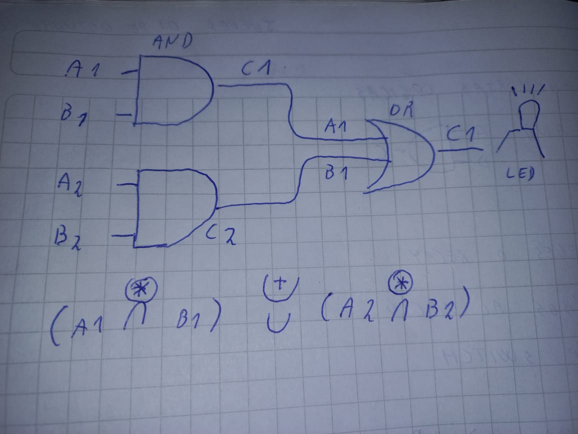

Transcribed Image Text:A1
ES
AND
CA
111/
A2
B₂
D
C2
+
A1
B1
DR
C1
R
(A1 & 01) & (82982)
U
(A2AB2)
LED
Expert Solution
This question has been solved!
Explore an expertly crafted, step-by-step solution for a thorough understanding of key concepts.

Step by stepSolved in 2 steps

Knowledge Booster

Similar questions
- not use ai pleasearrow_forwardQ2. A full-wave controlled rectifier circuit with resistive load shown below: Calculate the firing angle (a.) if it is required to obtain an average output voltage of 70% of the maximum possible average output voltage. • Sketch the output Vg & ig Waveform and determine the average current. 1:2 a, = 15 R= 302 Vs -V2x110 Sin 120nt cot VRarrow_forwardPlease answer in short I will like but please asap please urgent... Consider the circuit shown in the figure. Assume that each diode has a turn-on voltage of V_gamma = 0.6V. a) Determine R1, R2 and R3 such that, ID1 = 0.2mA, ID2 = 0.3mA and ID3 = 0.5mA. b) Find the voltage across V1, V2 and the current for each of the diodes for, R1 = 10kΩ, R2 = 4kΩ and R3 = 2.2kΩ.arrow_forward
- FAIRCHILD Discrete POWER & Signal Technologies SEMICONDUCTOR ru 1N4001 - 1N4007 Features • Low torward voltage drop. 10 a14 * High aurge eurrent cepablity. 0.160 4.06) DO 41 COLOR BAND DGNOTEs CAT-Cos 1.0 Ampere General Purpose Rectifiers Absolute Maximum Ratings T-26*Cuness atnerwioe rated Symbol Parameter Value Units Average Recttied Current 1.0 375" lead length a TA - 75°C Tsargei Peak Forward Surge Current 8.3 ms single halr-sine-wave Superimposed on rated load JEDEC method) 30 A Pa Total Device Dissipetion 2.5 20 Derste above 25°C Ra Tag Thermal Resistence, Junction to Amblent 5D Storage Temperature Range 55 to +175 -55 to +150 Operating Junetion Temperature PC "These rarings are imithg valuee above whien the serviceatity or any semiconductor device may te impaired. Electrical Characteristics T-20'Cunieas ofherwise roted Parameter Device Units 4001 4002 4003 4004 4005 4006 4007 Peak Repetitive Reverse Vellage Maximum RME votage DC Reverse Voltage Maximum Reverse Current @ rated VR…arrow_forwardill rate thank youarrow_forwardQ2) Consider the circuit below. The diodes D1 and D2 are Si diodes VD,=.7v , and R=10K , The Zener diodes have VZ1=4.3V , and VZ2=6.3V. The input voltage is Vin =10 sin(w;) . Sketch the output voltage for one cycle, carefully labelling important features of the plot such as maxima and minima. R A D2 vo D1 VI Vzi Vz2 +arrow_forward
- Q1(B) Prove that the single phase half wave rectifier with load inductive that:- [1+cos(+0)] vde Vmax 21 (10M) 100 FEarrow_forwardHelli. I only need the last part. Plotting power vs voltage if used as a solar cell and give the definition of fill factor. Tnxarrow_forwardFor the following circuit, assume the diodes are identical and ideal. Let V1 = 12V, V2 = 3V, R1 =6kΩ and R2 = 6kΩ. Assume that the diode voltages and currents follow the standard convention on polarity and direction. Solve ID1. Give your answer in units of Am but omit units. For the same circuit, what is VD1? Give your answer in units of Volts. For the same circuit, what is ID2? Give your answer in units of Am . For the same circuit, what is VD2? Give your answer in units of Volts.arrow_forward
- answer in 4 decimalsarrow_forwardPlease answer all the way through and with stepsarrow_forwardconsider the figure below that shows an approximated reverse recovery turn-off characteristics for a power diode. Show that the following relation can express the total reverse recovery charge, Qrr = 1/2(trr*ts1) di1/dt =1/2(trr*ts21) di2/dt * ip Isl 1s2! -Irarrow_forward
arrow_back_ios
SEE MORE QUESTIONS
arrow_forward_ios
Recommended textbooks for you
- Introductory Circuit Analysis (13th Edition)Electrical EngineeringISBN:9780133923605Author:Robert L. BoylestadPublisher:PEARSON
 Delmar's Standard Textbook Of ElectricityElectrical EngineeringISBN:9781337900348Author:Stephen L. HermanPublisher:Cengage Learning
 Programmable Logic ControllersElectrical EngineeringISBN:9780073373843Author:Frank D. PetruzellaPublisher:McGraw-Hill Education
  Fundamentals of Electric CircuitsElectrical EngineeringISBN:9780078028229Author:Charles K Alexander, Matthew SadikuPublisher:McGraw-Hill Education
 Electric Circuits. (11th Edition)Electrical EngineeringISBN:9780134746968Author:James W. Nilsson, Susan RiedelPublisher:PEARSON
 Engineering ElectromagneticsElectrical EngineeringISBN:9780078028151Author:Hayt, William H. (william Hart), Jr, BUCK, John A.Publisher:Mcgraw-hill Education,
Introductory Circuit Analysis (13th Edition)
Electrical Engineering
ISBN:9780133923605
Author:Robert L. Boylestad
Publisher:PEARSON
Delmar's Standard Textbook Of Electricity
Electrical Engineering
ISBN:9781337900348
Author:Stephen L. Herman
Publisher:Cengage Learning
Programmable Logic Controllers
Electrical Engineering
ISBN:9780073373843
Author:Frank D. Petruzella
Publisher:McGraw-Hill Education
Fundamentals of Electric Circuits
Electrical Engineering
ISBN:9780078028229
Author:Charles K Alexander, Matthew Sadiku
Publisher:McGraw-Hill Education
Electric Circuits. (11th Edition)
Electrical Engineering
ISBN:9780134746968
Author:James W. Nilsson, Susan Riedel
Publisher:PEARSON
Engineering Electromagnetics
Electrical Engineering
ISBN:9780078028151
Author:Hayt, William H. (william Hart), Jr, BUCK, John A.
Publisher:Mcgraw-hill Education,