
Delmar's Standard Textbook Of Electricity
7th Edition
ISBN: 9781337900348
Author: Stephen L. Herman
Publisher: Cengage Learning
expand_more
expand_more
format_list_bulleted
Related questions
Question
not use ai please don't
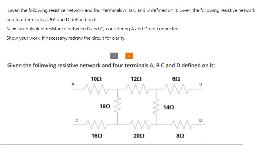

Transcribed Image Text:Given the following resistive network and four terminals A, B C and D defined on it: Given the following resistive network
and four terminals A, BC and D defined on it:
N = 6: equivalent resistance between B and C, considering A and D not connected.
Show your work. If necessary, redraw the circuit for clarity.
Given the following resistive network and four terminals A, B C and D defined on it:
1002
A
1802
1202
1402
602
B
سك
мо
1602
2002
802
Expert Solution
This question has been solved!
Explore an expertly crafted, step-by-step solution for a thorough understanding of key concepts.

Step by stepSolved in 2 steps with 3 images

Knowledge Booster

Similar questions
- (e) Create a list of components for the following circuit. 6v Vcc D1 R7 4k7 ZS D2 ( M RV1 470k C1 100nF 10µF C2 IC1 R2 150k RS Q4 Q5 Q4-Q14 R5 Q1 Q6 4. Q7 4k7 10 14 13 15 RTC Q8 Q9 4060 Q10 Q12 Q13 Q14 стс R1 100k _12 MR R4 4.7k R6 4.7k LED1 LED2arrow_forwardTrue False 0000000 ☐ ☐ ☐ ☐ ☐ ☐ ☐ Are the following statements about unloaded voltage dividers true or false? A voltage divider is a series connection of resistors. A voltage divider is a parallel connection of resistors. In a voltage divider, the currents through the resistors are equal. In a voltage divider, the currents through the resistors behave like the ratio of the resistors. In a voltage divider, the currents through the resistors behave like the ratio of the reciprocal values of the resistors. In a voltage divider, the voltages across the resistors are equal. In a voltage divider, the voltages across the resistors behave like the ratio of the resistors. In a voltage divider, the voltages across the resistors behave like the ratio of the reciprocal values of the resistors. П ☐arrow_forwardDraw bond graph model of the following system. R3 C3 T3 R2 C2 93 R1 C1 92 To N T1 T2arrow_forward
- Using these diagrams of circuits, what are the steps and materis to create these kind of circuits?arrow_forwardPart B Given the following circuit F1 SW1 SW2 Sw3 SW4 SW5 SW6 BAT1 R1 R2 R3 R4 R5 R6 12 V 12 0 24 0 48 0 00arrow_forwardR2 Q1 ... VCC R1 Show your complete solution. Use two decimal places for your final answer. Calculate the value of RC in ohms. at VCC=18 V, IB=26 uA, and VC=7V and B=69arrow_forward
- How would I approach this question? Do I need to use Kirchoff's junction rules or can I just subtract the voltage drop?arrow_forwardSolve for the resistancesarrow_forwardUse Kirchhoff's Law to solve for the current passing through each resistor. Compare it with what you got from the PHET Simulation A D 392 www 6V E www F 192 www 292 352 www 9V B Carrow_forward
- Kindly answer all of the questions please, I will rate you with like/upvote. Please answer all of the questions. Thank you so much.arrow_forwardQuestion 2 Figure Q2 shows the exact equivalent circuit of a 50 Hz, 30 kVA, 2200 V/250 V single- phase transformer. Given that Rp = 0.9 №, Xp = 2 N, Rc = 10 MN, Xm 13 ΜΩ, Rς = 0.0094 , Xs 0.038 N and iron losses at the rated voltage is 10 kW. A load with 0.8 lagging is connected to the secondary circuit of the transformer. ܫܫܫܫ (b) - (a) Draw the approximate equivalent circuit referred to primary and calculate the equivalent winding resistance and reactance referred to primary. Based on the circuit parameters calculated in part (a), determine the full load efficiency.arrow_forwardplease show clear step by step working how you got the answer thank youarrow_forward
arrow_back_ios
SEE MORE QUESTIONS
arrow_forward_ios
Recommended textbooks for you
- Delmar's Standard Textbook Of ElectricityElectrical EngineeringISBN:9781337900348Author:Stephen L. HermanPublisher:Cengage Learning
Delmar's Standard Textbook Of Electricity
Electrical Engineering
ISBN:9781337900348
Author:Stephen L. Herman
Publisher:Cengage Learning