Introductory Circuit Analysis (13th Edition)
13th Edition
ISBN: 9780133923605
Author: Robert L. Boylestad
Publisher: PEARSON
expand_more
expand_more
format_list_bulleted
Question

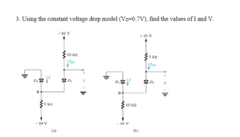
Transcribed Image Text:3. Using the constant voltage drop model (VD=0.7V), find the values of I and V.
+10 V
B
5 kn
-10 V
10 ΚΩ
102
D
+10 V
5 kg
lo
DIZ
D₂
B
10 kn
-10 V
(a)
(b)
Expert Solution
This question has been solved!
Explore an expertly crafted, step-by-step solution for a thorough understanding of key concepts.
Step by stepSolved in 2 steps with 1 images

Knowledge Booster
Similar questions
- The figure shows a circuit that contains five identical resistors with resistance R = 10 ohms, one inductors with inductance L = 4 mH, and an ideal battery with emf = 14V. What is the current I in Amp through the battery long after the switch is closed? R 14 4, mm M Select one: Oa. 2.80A Ob. 0.40A Oc. 9.80A Od. 4.90A Oe. 245Aarrow_forwardCan you please do (c) Calculate the total power consumption of your circuit. I attached a photo of the circuit ectarrow_forwardHelp me answer, I want to check my solution To get the contribution of the 75V source to iR, we first kill the 50mA source. What is the resulting equivalent resistance in series with the 75K resistor (in Kohms) To get the contribution of the 75V source to iR, we first kill the 50mA source. What is the resulting value of iR (in mA)? What is the nodal equation for Vx? What is the Thevanin voltage in (Volts) and Thevanin resistance in (Kohms)?arrow_forward
- Two silicon diodes, with a forward voltage drop of 0.7 V, are used in the circuit shown in the figure. The range of input vi for which the output voltage vo = vi, is. R ww D₁ A -1V(+ D₂ +)3Varrow_forwardA 150V moving iron volt meter intended for 50Hz has an inductance of 0.7H and a resistance of 3K ohm. Find the series resistance required to extend the range of instrument to 300V if this 300V - 50Hz instrument used to measure dc voltage find the dc voltage when the scale reading is 200Varrow_forwardThe circuit in the figure below contains two resistors, R1 = 4.00kΩ and R2 = 5.00kΩ, and two capacitors, C1 = 4.00uF and C2 = 5.00uF, connected to a battery with emf E = 120V. If no charges exist on the capacitors before switch S is closed, determine the charge q1 on capacitor C1 1.00ms after the switch is closed. Determine the charge q2 on capacitor C2 1.00ms after the switch is closed.arrow_forward
- In the circuit shown below, if VA= 1V and V-2V, the statuses of the diodes are (Assuming ideal diodes) D₁ VA V₂₁ D₂ ERL Vout Select one: O a D₂ is ON, D₂ is ON O b. None of these Oc. Dy is OFF, D₂ is ON O d. Dy is ON, D₂ is OFFarrow_forwardPlease show step by step working with neat sketch of the graph thank you.(please handwrite solutions)arrow_forwardDon't use chat gpt It Chatgpt means downvotearrow_forward
- Please in typing format please ASAP for the like please clear the Please answer in typing format please ASAP for please ASAP for likearrow_forward1. A solar cell has reverse saturation current is lo =4.3x 10 10 A and short- circuit current Isc = 3 A at 25 C. Parallel resistance Rs= 20 Q and series resistance RS = 0.05 Q. Find the cell current, open circuit voltage and voltage when the junction voltage is 0.45V. %3Darrow_forwardYou can assume any values just please note them. I just want to have this circuit working at all conditions. Or at least see the process so I can do it on my own with my own calculationsarrow_forward
arrow_back_ios
SEE MORE QUESTIONS
arrow_forward_ios
Recommended textbooks for you
 Introductory Circuit Analysis (13th Edition)Electrical EngineeringISBN:9780133923605Author:Robert L. BoylestadPublisher:PEARSON
 Delmar's Standard Textbook Of ElectricityElectrical EngineeringISBN:9781337900348Author:Stephen L. HermanPublisher:Cengage Learning
 Programmable Logic ControllersElectrical EngineeringISBN:9780073373843Author:Frank D. PetruzellaPublisher:McGraw-Hill Education
 Fundamentals of Electric CircuitsElectrical EngineeringISBN:9780078028229Author:Charles K Alexander, Matthew SadikuPublisher:McGraw-Hill Education
 Electric Circuits. (11th Edition)Electrical EngineeringISBN:9780134746968Author:James W. Nilsson, Susan RiedelPublisher:PEARSON
 Engineering ElectromagneticsElectrical EngineeringISBN:9780078028151Author:Hayt, William H. (william Hart), Jr, BUCK, John A.Publisher:Mcgraw-hill Education,

Introductory Circuit Analysis (13th Edition)
Electrical Engineering
ISBN:9780133923605
Author:Robert L. Boylestad
Publisher:PEARSON

Delmar's Standard Textbook Of Electricity
Electrical Engineering
ISBN:9781337900348
Author:Stephen L. Herman
Publisher:Cengage Learning

Programmable Logic Controllers
Electrical Engineering
ISBN:9780073373843
Author:Frank D. Petruzella
Publisher:McGraw-Hill Education

Fundamentals of Electric Circuits
Electrical Engineering
ISBN:9780078028229
Author:Charles K Alexander, Matthew Sadiku
Publisher:McGraw-Hill Education

Electric Circuits. (11th Edition)
Electrical Engineering
ISBN:9780134746968
Author:James W. Nilsson, Susan Riedel
Publisher:PEARSON

Engineering Electromagnetics
Electrical Engineering
ISBN:9780078028151
Author:Hayt, William H. (william Hart), Jr, BUCK, John A.
Publisher:Mcgraw-hill Education,