
Elements Of Electromagnetics
7th Edition
ISBN: 9780190698614
Author: Sadiku, Matthew N. O.
Publisher: Oxford University Press
expand_more
expand_more
format_list_bulleted
Related questions
Question
thumb_up100%

Transcribed Image Text:### Problem Overview
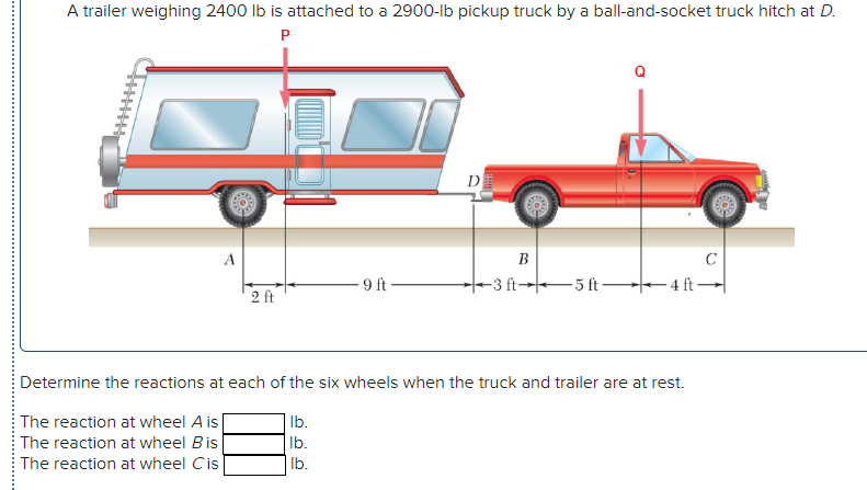
A trailer weighing 2400 lb is attached to a 2900 lb pickup truck by a ball-and-socket truck hitch at point \( D \).
### Diagram Explanation
This diagram shows the side view of a trailer and a pickup truck connected together. Key components and their positions are as follows:
- **Point P:** Represents the center of gravity of the trailer. It is marked with a vertical red arrow, indicating the trailer's weight force.
- **Point Q:** Represents the center of gravity of the pickup truck. It is marked with another vertical red arrow, indicating the truck's weight force.
- **Hitch at D:** This is where the trailer is attached to the truck.
### Measurement Distances
- **From wheel A to point P:** 2 ft
- **From P to wheel B:** 9 ft
- **Between wheels B and D:** 3 ft
- **From wheel D to Q:** 5 ft
- **From Q to wheel C:** 4 ft
### Objective
Determine the reactions at each of the six wheels when the truck and trailer are at rest.
- **The reaction at wheel A:** _____ lb
- **The reaction at wheel B:** _____ lb
- **The reaction at wheel C:** _____ lb
### Instructions
To solve this problem, you will calculate the vertical reactions at the wheels (A, B, C) caused by the static forces of the trailer and truck. Use principles from static equilibrium, accounting for the weights and distances between the points of interest.
---
Expert Solution
This question has been solved!
Explore an expertly crafted, step-by-step solution for a thorough understanding of key concepts.

This is a popular solution

Trending nowThis is a popular solution!

Step by stepSolved in 4 steps with 2 images

Knowledge Booster


Learn more about
Need a deep-dive on the concept behind this application? Look no further. Learn more about this topic, mechanical-engineering and related others by exploring similar questions and additional content below.Similar questions
- Only Handwritten,it should not be Typed.arrow_forwardFor what value M of the clockwise couple will the horizontal component Ax of the pin reaction at A be zero? If a couple of that same magnitude M were applied in a counterclockwise direction, what would be the value of Ax? Answers: M= A Ax= i i -2.4° 170 lb L--x -2.4 B M 1.9' 64° lb-ft lb 1.9' Carrow_forwardI need a quick answerarrow_forward
- The uniform bar AB shown in Fig. 30 lb. If the spring is unstretched when 8 = 0°, determine the angle 0 for equilibrium if k = 15 lb/ft and L = 3 ft. weighs B.arrow_forward3/C Draw a complete and correct free-body diagram of each of the bodies designated in the statements. The weights of the bodies are sigmificant only if the mass is stated. All forces, known and unknown, should be labeled. (Note: The sense of some reaction components cannot always be determined without numerical calculation.)arrow_forwardHELP!!!! Be sure answer all and Clearly written. Directions: Free Body Diagrams (FBD) must be included for equilibrium problemsarrow_forward
arrow_back_ios
arrow_forward_ios
Recommended textbooks for you
- Elements Of ElectromagneticsMechanical EngineeringISBN:9780190698614Author:Sadiku, Matthew N. O.Publisher:Oxford University Press
 Mechanics of Materials (10th Edition)Mechanical EngineeringISBN:9780134319650Author:Russell C. HibbelerPublisher:PEARSON
 Thermodynamics: An Engineering ApproachMechanical EngineeringISBN:9781259822674Author:Yunus A. Cengel Dr., Michael A. BolesPublisher:McGraw-Hill Education
  Control Systems EngineeringMechanical EngineeringISBN:9781118170519Author:Norman S. NisePublisher:WILEY
 Mechanics of Materials (MindTap Course List)Mechanical EngineeringISBN:9781337093347Author:Barry J. Goodno, James M. GerePublisher:Cengage Learning
 Engineering Mechanics: StaticsMechanical EngineeringISBN:9781118807330Author:James L. Meriam, L. G. Kraige, J. N. BoltonPublisher:WILEY
Elements Of Electromagnetics
Mechanical Engineering
ISBN:9780190698614
Author:Sadiku, Matthew N. O.
Publisher:Oxford University Press
Mechanics of Materials (10th Edition)
Mechanical Engineering
ISBN:9780134319650
Author:Russell C. Hibbeler
Publisher:PEARSON
Thermodynamics: An Engineering Approach
Mechanical Engineering
ISBN:9781259822674
Author:Yunus A. Cengel Dr., Michael A. Boles
Publisher:McGraw-Hill Education
Control Systems Engineering
Mechanical Engineering
ISBN:9781118170519
Author:Norman S. Nise
Publisher:WILEY
Mechanics of Materials (MindTap Course List)
Mechanical Engineering
ISBN:9781337093347
Author:Barry J. Goodno, James M. Gere
Publisher:Cengage Learning
Engineering Mechanics: Statics
Mechanical Engineering
ISBN:9781118807330
Author:James L. Meriam, L. G. Kraige, J. N. Bolton
Publisher:WILEY