
Structural Analysis
6th Edition
ISBN: 9781337630931
Author: KASSIMALI, Aslam.
Publisher: Cengage,
expand_more
expand_more
format_list_bulleted
Related questions
Concept explainers
Question
A rectangular foundation 4 m x 6 m (Figure 1) transmits a stress of 100 kPa on the surface of a soil deposit. Plot the distribution of increases of vertical stresses with depth under points A, B, and C up to a depth of 20 m. At what depth is the increase in vertical stress below A less than 10% of the surface stress?
Can I get a detailed explanation to the solution of this question?
Including the finding of as and the graphs and finding the surface stress, load and increase in stress using the oz=4qsI method
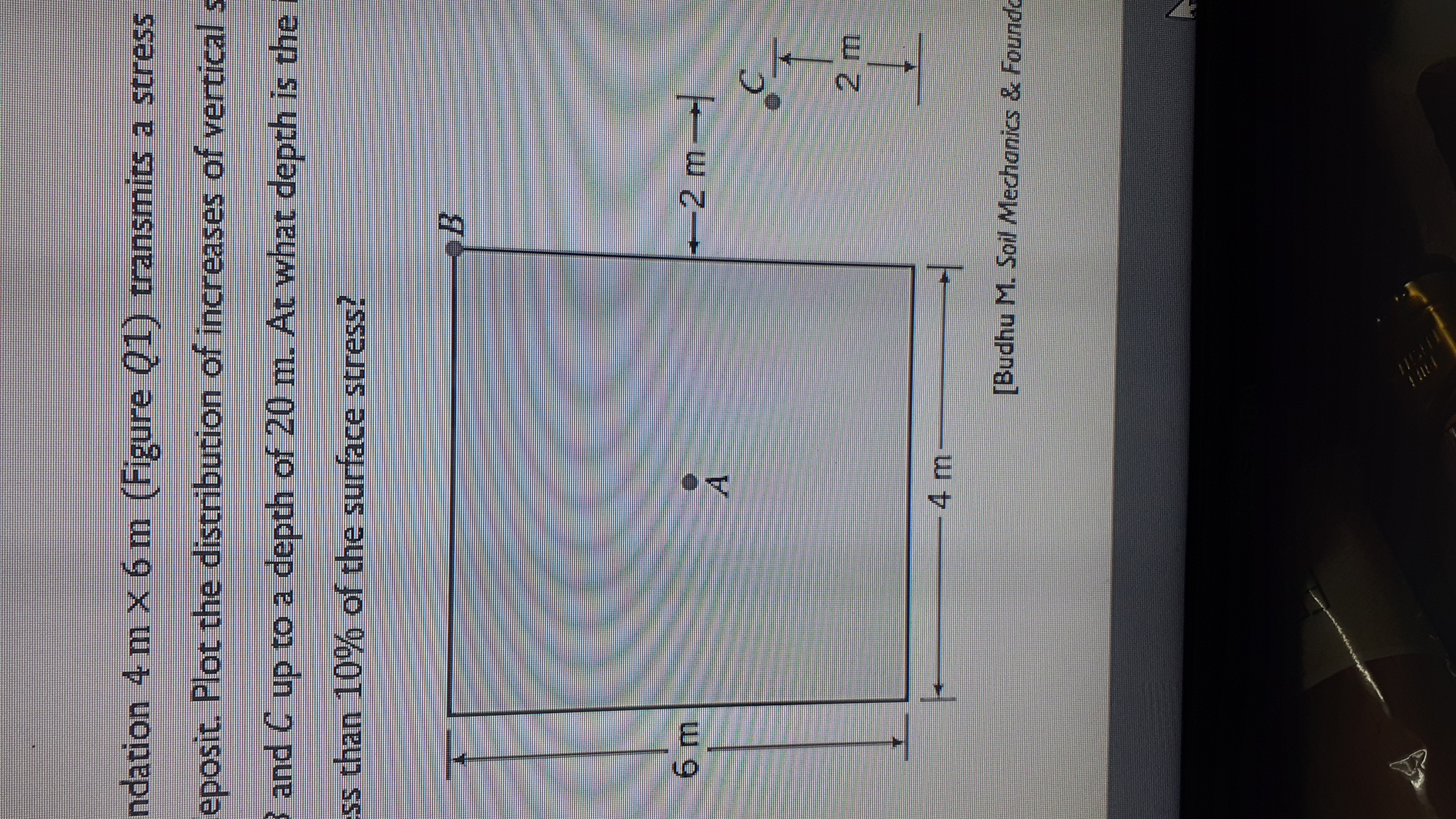

Transcribed Image Text:ndation 4 m X 6 m (Figure Q1) transmits a stress
eposit. Plot the distribution of increases of vertical
3 and C up to a depth of 20 m. At what depth is the i
ss than 10% of the surface stress?
+2 m
A.
[Budhu M. Soil Mechanics & Foundo
Expert Solution
This question has been solved!
Explore an expertly crafted, step-by-step solution for a thorough understanding of key concepts.

This is a popular solution

Trending nowThis is a popular solution!

Step by stepSolved in 3 steps

Knowledge Booster


Learn more about
Need a deep-dive on the concept behind this application? Look no further. Learn more about this topic, civil-engineering and related others by exploring similar questions and additional content below.Similar questions
- 10.11 Refer to Figure 10.41. Due to application of line loads q, and q2, the vertical stress increase at point A is 42 kN/m². Determine the magnitude of q2. 91 = 292 kN/m 92 450 4.5 m 3 m- 3 m Figure 10.41 © Cengage Learning 2014arrow_forwardA circular foundation 2m in diameter is shown in the figure below. A normally consolidated clay layer 5m thick is located below the foundation. Determine the consolidation settlement of the clay. method 2:1 As one layer of clay of 5m thick: Divide the clay layer into (5) sub-layers each of 1m thick:Calculation of increase of stress below the center of each sub-layer Δσ ⃘(i): Weighted average pressure increase (Simpson's rule): "note in the picture solve the question but please solve in method 2:1"arrow_forwardFrom the given soil element, using the graphical method (Mohr's circle), determine the following: A) The values for the maximum and minimum principal stresses (0₁ and 3) B) The location of the pole C) The normal stress (a) and shear stress (ta) on the shear plane (dashed red line) D) In your own words and no more than a few sentences, explain the advantage of identifying the pole's location in a Mohr's circle graphical analysis. 40° 0 = 8 kPa Y -T₁ = 3 kPa yx T = -3 kPa xy o = 2 kPa Xarrow_forward
- only HANDWRITTEN answer needed ( NOT TYPED)arrow_forwardFrom the following given soil element, using the graphical method (Mohr’s circle),determine 1) the maximum and minimum principal stresses, 2) maximum shear stress,and 3) the normal and shear stresses on plane AB (assume to be the failure surface).Confirm your answer with analytical equations.Please practice more problems from your textbook.arrow_forwardGiven An 3 m by 4 m rectangular area carrying a uniform load of 205 kN/m2 is applied to the ground surface. Required What is the vertical stress increment due to the uniform load at a depth of 10 m below the middle of the long edge? Provide answer in kN/m², to the nearest 100th. Your Answer:arrow_forward
- A rectangular foundation 4 m x 6m (Figure P1.20) trans- mits a stress of 100 kPa on the surface of a soil deposit. Plot the distribution of increases of vertical stresses with depth under points A, B, and C up to a depth of 20 m. At what depth is the increase in vertical stress below A less than 10% of the surface stress? -2 m- 2 m 4 m-arrow_forwardStresses in Soil Mass: Mohr's Circle 131.6 kPa 53.6 kPa 315.2 kPa 315.2 kPa 35 131.6 kPa 2. Find Normal and Shear Stress at Failure Plan A-B. Enter your answer to three significant figures. (1 decimal place)arrow_forward6.8 Refer to Figure P6.8. Using the procedure outlined in Section 6.8, determine the average stress increase in the clay layer below the center of the foundation due to the net foundation load of 50 ton. [Use Eq. (6.28).] 4:5 ft 3 ft 50 ton (net load) 10 ft 5 ft x 5 ft Sand y=100 lb/ft! Sand Yat=122 lb/ft³ Groundwater table Ysat ⇒120 lb/ft³ = 0.7 C=0.25 -C, 0,06 Preconsolidation pressure = 2000 lb/ft² Figure P6.8arrow_forward
- A butt weld is set on the cross section of an I-shaped beam. The re are bending moment M ard sheao forne V at the speicing position, where Ma || 20 KN m and v 374KN The beam is made of Q355 b steel and semi- automatic weld is used with welding rod E50. The des ign value of the weld tensile to Strength f" is 260 N/mnm?. c heek whethe please The stregth of the butt weld is safe by eloulation. ET 3.arrow_forwardG1 PLEASE HELParrow_forwardi need the answer quicklyarrow_forward
arrow_back_ios
SEE MORE QUESTIONS
arrow_forward_ios
Recommended textbooks for you
 Structural Analysis (10th Edition)Civil EngineeringISBN:9780134610672Author:Russell C. HibbelerPublisher:PEARSON
 Principles of Foundation Engineering (MindTap Cou...Civil EngineeringISBN:9781337705028Author:Braja M. Das, Nagaratnam SivakuganPublisher:Cengage Learning
 Fundamentals of Structural AnalysisCivil EngineeringISBN:9780073398006Author:Kenneth M. Leet Emeritus, Chia-Ming Uang, Joel LanningPublisher:McGraw-Hill Education
 Traffic and Highway EngineeringCivil EngineeringISBN:9781305156241Author:Garber, Nicholas J.Publisher:Cengage Learning
Structural Analysis (10th Edition)
Civil Engineering
ISBN:9780134610672
Author:Russell C. Hibbeler
Publisher:PEARSON
Principles of Foundation Engineering (MindTap Cou...
Civil Engineering
ISBN:9781337705028
Author:Braja M. Das, Nagaratnam Sivakugan
Publisher:Cengage Learning
Fundamentals of Structural Analysis
Civil Engineering
ISBN:9780073398006
Author:Kenneth M. Leet Emeritus, Chia-Ming Uang, Joel Lanning
Publisher:McGraw-Hill Education
Traffic and Highway Engineering
Civil Engineering
ISBN:9781305156241
Author:Garber, Nicholas J.
Publisher:Cengage Learning