
Elements Of Electromagnetics
7th Edition
ISBN: 9780190698614
Author: Sadiku, Matthew N. O.
Publisher: Oxford University Press
expand_more
expand_more
format_list_bulleted
Related questions
Concept explainers
Question
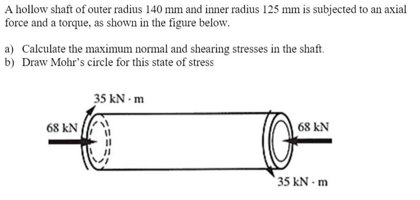

Transcribed Image Text:A hollow shaft of outer radius 140 mm and inner radius 125 mm is subjected to an axial
force and a torque, as shown in the figure below.
a) Calculate the maximum normal and shearing stresses in the shaft.
b) Draw Mohr’s circle for this state of stress
35 kN - m
68 kN
68 kN
35 kN - m
Expert Solution
This question has been solved!
Explore an expertly crafted, step-by-step solution for a thorough understanding of key concepts.

This is a popular solution

Trending nowThis is a popular solution!

Step by stepSolved in 3 steps with 1 images

Knowledge Booster


Learn more about
Need a deep-dive on the concept behind this application? Look no further. Learn more about this topic, mechanical-engineering and related others by exploring similar questions and additional content below.Similar questions
- 3- a. Determine the ditribution of shear stress in the following circular shafts that are subject to a maximum torque of 7.5 Nm by calculating the polar second moment of area. a) b) a) O b) O b. Using the previous answers; determine the angular deflection in both shafts. Both shafts are 20 cm long and the modulus of rigidity for the material is 60GN/m^2. O R R O R R = 5mm r = 3mm R = 5mm r = 3mmarrow_forwardA shaft composed of three segments and fastened to rigid supports. Determine the maximum shear stress developed in each segment. (Please don't skip any mathematical step and please show all the working)arrow_forwardA shaft is subjected to a torque of 28 kNm and a maximum bending moment of 25 kNm. The shaft is solid with a diameter of 125 mm. Using the Mohr circle method find the values for the principal stresses and themaximum shear stresses on the shaft i)Construct the Mohr circle on the graph paper provided. ii) Using the Mohr circle method find the values for the principal stresses and the maximum shear stresses on the shaft.iii) Show the orientations of the planes on which the principal stresses act on a rotatedelementarrow_forward
- For the beam shown in the figure: Determine the normal and shear stress at a point located at 4.5 ft from support B and 4 inches from the top of the section. Draw the Mohr's circle for the stresses at that point and calculate the principal stresses and the max in plane shear stress as well as their directions. Show these stresses on appropriately oriented elements. A 1600 lb 1.5 ft 80 lb/ft -9 ft B 1.5 in. 4 in 11.5 in.arrow_forwardThe shaft in Figure below consists of a 3-in. -diameter aluminum segment that is rigidly joined to a 2-in. -diameter steel segment. The ends of the shaft are attached to rigid supports, Calculate the maximum shear stress developed in each segment when the torque T= 10 kip.in is applied. Use G = 4×10⁶ psi for aluminum and G = 12×106 psi for steel. Aluminum 3-in. diameter 6 ft T Steel 2-in. diameter 3 ftarrow_forwardWhen a steel rod below is subjected to torque (T = 1 kN · m) and bending moment (M = 4 kN · m) simultaneously, calculate equivalent stresses using Tresca's theory and Von-Mises' theory 2. M M 50mmarrow_forward
arrow_back_ios
arrow_forward_ios
Recommended textbooks for you
- Elements Of ElectromagneticsMechanical EngineeringISBN:9780190698614Author:Sadiku, Matthew N. O.Publisher:Oxford University Press
 Mechanics of Materials (10th Edition)Mechanical EngineeringISBN:9780134319650Author:Russell C. HibbelerPublisher:PEARSON
 Thermodynamics: An Engineering ApproachMechanical EngineeringISBN:9781259822674Author:Yunus A. Cengel Dr., Michael A. BolesPublisher:McGraw-Hill Education
  Control Systems EngineeringMechanical EngineeringISBN:9781118170519Author:Norman S. NisePublisher:WILEY
 Mechanics of Materials (MindTap Course List)Mechanical EngineeringISBN:9781337093347Author:Barry J. Goodno, James M. GerePublisher:Cengage Learning
 Engineering Mechanics: StaticsMechanical EngineeringISBN:9781118807330Author:James L. Meriam, L. G. Kraige, J. N. BoltonPublisher:WILEY
Elements Of Electromagnetics
Mechanical Engineering
ISBN:9780190698614
Author:Sadiku, Matthew N. O.
Publisher:Oxford University Press
Mechanics of Materials (10th Edition)
Mechanical Engineering
ISBN:9780134319650
Author:Russell C. Hibbeler
Publisher:PEARSON
Thermodynamics: An Engineering Approach
Mechanical Engineering
ISBN:9781259822674
Author:Yunus A. Cengel Dr., Michael A. Boles
Publisher:McGraw-Hill Education
Control Systems Engineering
Mechanical Engineering
ISBN:9781118170519
Author:Norman S. Nise
Publisher:WILEY
Mechanics of Materials (MindTap Course List)
Mechanical Engineering
ISBN:9781337093347
Author:Barry J. Goodno, James M. Gere
Publisher:Cengage Learning
Engineering Mechanics: Statics
Mechanical Engineering
ISBN:9781118807330
Author:James L. Meriam, L. G. Kraige, J. N. Bolton
Publisher:WILEY