
Power System Analysis and Design (MindTap Course List)
6th Edition
ISBN: 9781305632134
Author: J. Duncan Glover, Thomas Overbye, Mulukutla S. Sarma
Publisher: Cengage Learning
expand_more
expand_more
format_list_bulleted
Related questions
Question
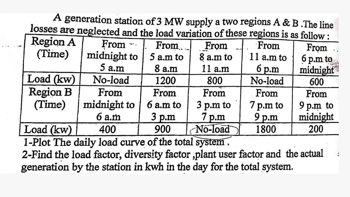

Transcribed Image Text:A generation station of 3 MW supply a two regions A & B .The line
losses are neglected and the load variation of these regions is as follow:
Region A
(Time)
11 a.m
From
11 a.m to
6 p.m
No-load
From
midnight to
From
5 a.m to
From
8 a.m to
Load (kw)
5 a.m
No-load
8 a.m
1200
800
Region B
(Time)
From
From
midnight to
6 a.m to
3 p.m to
7 p.m to
6 a.m
3 p.m
7p.m
9 p.m
Load (kw)
400
900
No-load
1800
From
From
From
6 p.m to
midnight
600
From
9 p.m to
midnight
200
1-Plot The daily load curve of the total system.
2-Find the load factor, diversity factor,plant user factor and the actual
generation by the station in kwh in the day for the total system.
Expert Solution
This question has been solved!
Explore an expertly crafted, step-by-step solution for a thorough understanding of key concepts.

Step by stepSolved in 2 steps with 1 images

Knowledge Booster

Similar questions
- The circuit shows an unbalanced electrical installation powered by a positive sequence symmetrical three-phase network of 380 V compound voltage. The loads are single phase. Load 1 absorbs an active power of 950 W with f.d.p. 0.5 inductive. Load 2 absorbs an active power of 1,140 W with f.d.p. Unit. Load 3 absorbs from the network an active power of 760 W with f.d.p. 0.5 capacitive. Taking the network voltage URN as the phase reference, calculate: a) complex expressions of the line currents IR. Is. and ITarrow_forward41. Two ac sources feed a common variable resistive load as shown in figure. Under the maximum power transfer condition, the power absorbed by the load resistance R, is lall 6 2 j8 2 6 2 11020 ( 0706 O9020° (a) 2200 W (b) 1250 W (c) 1000 W (d) 625 Warrow_forward4) Therenin's Equinlena Circuit and Marimum Poer truns fer Thiorem a) For the Circuit derive the given in the figure, therenin's eq uivalence Circuit acrass the branch witn the loud impedanu. b) Culculate to deliver the volue of the load Impedanca makimum power to the load, c) caleula te the Power dissipa ted through the loud, 72arrow_forward
- A single-phase, 120V(rms),60Hz source supplies power to a series R-L circuit consisting of R=10 and L=40mH. (a) Determine the power factor of the circuit and state whether it is lagging or leading. (b) Determine the real and reactive power absorbed by the load. (c) Calculate the peak magnetic energy Wint stored in the inductor by using the expression Wint=L(Irms)2 and check whether the reactive power Q=Wint is satisfied. (Note: The instantaneous magnetic energy storage fluctuates between zero and the peak energy. This energy must be sent twice each cycle to the load from the source by means of reactive power flows.)arrow_forwardLet a 100V sinusoidal source be connected to a series combination of a 3 resistor, an 8 inductor, and a 4 capacitor. (a) Draw the circuit diagram. (b) Compute the series impedance. (C) Determine the current I delivered by the source. Is the current lagging or leading the source voltage? What is the power factor of this circuit?arrow_forward60. An RLC series circuit connected to a 110-volt and 50-cycle AC source, contains the following series resistances and reactances: R1=10 ohm, R2= 15, XL1=20 ohms, XL2=25 ohms, XC= 40 ohms. Find the real power. a. 65.3899 b. 392.4372 c. 397.848 d. 588.6559arrow_forward
- what are load values in this power flow systemarrow_forwardShow the solution Using 24v AC source design a 24v unregulated power supply circuit that will power a 1kohms load with 50mv ripple. Draw your designed unregulated power supply circuitarrow_forward8. The total power supplied to a balance delta load is found in the same way as for a balance wye load. True False Either Neither 12. A load of 20 + j35 ohms is connected across a 220 V, 60 Hz supply. Find the reactive power of the load in var. 595 2420 1042 1382 13. A type of DC source where the characteristic output voltage has perfect unidirectional waveform and is based on electrochemical principle. Generator Inverter Converter Battery 14. Calculate the Rf of a circuit whose impedance is 20+j35 and current of 2A. 0.86 0.91 0.50 0.71 15. What capacitor shall be installed in parallel with a circuit to achieve a unity power factor if the reactive power of a circuit is 200VARS and the voltage is 100V. 80.45 microfarad 53.05 microfarad It's already in unity 62.45 microfaradarrow_forward
- two generators supplying a load. Generator I has a no-load frequency of 62.5 Hz and a slope Sp1 of I MW/Hz. Generator 2 has a no-load frequency of 62.0 Hz and a slope sp2 of I MW/Hz. The two generators are supplying a real load totaling 2.5 MW at 0.8 PF lagging. (a) At what frequency is this system operating, and how much power is supplied by each of the two generators? (b) Suppose an additional I-MW load were attached to this power system. What would the new system frequency be, and how much power would Gl and G2 supply now? Generator 1 VT V2 Generator 2 VTí KVAR KVARarrow_forwardAssume that the voltage applied to a load is V = 208- 30° V and the current flowing through the load is I = 5415° A a. Calculate the complex power S consumed by this load. b. Is this load inductive or capacitive? c. Calculate the power factor of this load. d. Calculate the reactive power consumed or supplied by this load. Does the load consume reactive power from the source or supply it to the source?arrow_forwardA generating station has the following daily load cycle: [10] Time 0-6 6-10 10-12 12-16 16-20 20-24 (Hours) Load 40 50 60 50 70 40 (MW) Draw the load curve and find (i) maximum demand (ii) units generated per day (iii) average load and (iv) load factor.arrow_forward
arrow_back_ios
SEE MORE QUESTIONS
arrow_forward_ios
Recommended textbooks for you
- Power System Analysis and Design (MindTap Course ...Electrical EngineeringISBN:9781305632134Author:J. Duncan Glover, Thomas Overbye, Mulukutla S. SarmaPublisher:Cengage Learning
Power System Analysis and Design (MindTap Course ...
Electrical Engineering
ISBN:9781305632134
Author:J. Duncan Glover, Thomas Overbye, Mulukutla S. Sarma
Publisher:Cengage Learning