Delmar's Standard Textbook Of Electricity
7th Edition
ISBN: 9781337900348
Author: Stephen L. Herman
Publisher: Cengage Learning
expand_more
expand_more
format_list_bulleted
Question
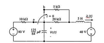
In the circuit in Figure 1 the switch has been in position a for a long time and in t=0 it changes to position b,
Taking into account the above, it is requested:
a) Simulate the voltage in the capacitor and the current in the coil for times t<0 when it is in a steady state. b) Simulate the voltage in the capacitor and the current in the coil for times t>0 until it reaches the state
stable (permanent regime). In addition, obtain the initial voltage of the coil and the initial current of the
capacitor right after the change.
c) Obtain the equations of voltage in the capacitor and current in the coil and then elaborate their
corresponding graphs.

Transcribed Image Text:10 ΚΩ
80 V
125
64
F
b
5 ΚΩ
t=0
iL(t)
20 ΚΩ
5H
+
Vc(t)
40 V
+
Expert Solution
This question has been solved!
Explore an expertly crafted, step-by-step solution for a thorough understanding of key concepts.
Step by stepSolved in 2 steps

Knowledge Booster
Similar questions
- Which ane oli the functions given below is a solton of the UL dy 2y dx None of These In y + 2 In x =c x²+c X+C 2arrow_forwardISMA 3K un 3K un + Vs 7mH 3√1₂ Im mn SmH -+ 20 V t IMF Vc What is Vs. iz Ve at steady-state?arrow_forwardv (V) AAA Determine the current flowing through a 7 nF capacitor. (You must provide an answer before moving on to the next part.) The current through the 7 nF capacitor is sin Trt nA. aptive YNC 135 A 117 cecece cox cecece cecrete ▬▬ Q Search -- Extr REYEEEEE um ET CELLE C 0:50 K G 3 Parrow_forward
- Please solve it.arrow_forwardFor the circuit shown, if R1=R2=Rc=10Kohm, RE=1Kohm. Rth as shown from the base is HH R₂ Vec Re RE H C₂ 5kohm O 8.5kOhm O 7.2kohm O 8kohm Oarrow_forwardSOLVE STEP BY STEP IN DIGITAL FORMAT For the following circuit, graph the output voltage vo(t) when the input voltage is a square waveform as shown. Assume that the capacitor, once charged, does not download. +10V -15И ** Vin (t) ( (Vin) C DA 5V Vo www + R vo(t)arrow_forward
- > * For the circuit shown, Vc voltge is * en mog C₁ HH 10 µF O -4.48V O -3.48V O -5.48V : O -2.48V Re 100 kQ Rc1.2kQ C₂ 16 10 pF B=45 9 Varrow_forwardi need the answer quicklyarrow_forwardDetermine the Thevenin open-circuit voltage in the figure below as seen from terminals a-b. j4 2 V. ell o a -j2 Q 5/0° A 0.2V, 4Ω O 7.3524-72.9° V 73.52472.9° V O 7.352279.2° V O 7.352272.9° V O 735.2472.9° mV wwarrow_forward
- Thanks and please do the these. Thanksarrow_forwardFind the charge q(t) on the capacitor and the current i(t) in the given LRC-series circuit. L = 1 h, R = 100 , C = 0.0004 f, E(t) = 40 V, q(0) = 0 C, ¡(0) = 3 A q(t) i(t) = = 3e 2 125 e -50t Need Help? -50t + 11 -50t 5 te -50t 110te Read It + A 2 125 Find the maximum charge on the capacitor. (Round your answer to four decimal places.) 2.2 хс Carrow_forward6) What is the equivalent capacitance for the following?arrow_forward
arrow_back_ios
SEE MORE QUESTIONS
arrow_forward_ios
Recommended textbooks for you
 Delmar's Standard Textbook Of ElectricityElectrical EngineeringISBN:9781337900348Author:Stephen L. HermanPublisher:Cengage Learning

Delmar's Standard Textbook Of Electricity
Electrical Engineering
ISBN:9781337900348
Author:Stephen L. Herman
Publisher:Cengage Learning