Computer Networking: A Top-Down Approach (7th Edition)
7th Edition
ISBN: 9780133594140
Author: James Kurose, Keith Ross
Publisher: PEARSON
expand_more
expand_more
format_list_bulleted
Question
Please could I have the written solution for this question.

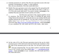
Transcribed Image Text:a) Calculate parameters E, and R, of the Thevenin equivalent circuit at the load
terminals corresponding to voltage V2 using equations
Show all your calculations. Fill-in the results table below.
b) Modify Thevenin equivalent circuit in the original Tina file and perform DC
analysis to confirm that the voltages on the loads are the same, i.e. that V2 =
V2e. Fill in the results table below. You need to include a screenshot of the
modified Thevenin equivalent circuit to justify your results.
find Thevenin equivalent of the original amplifier circuit
by simulation. This can be done in two steps: (1) Calculate the open circuit
voltage between the terminals Et ; (2) Set all sources to zero and then find the total
resistance between the two terminals Rt. You may find it useful to consult the
online course Free AC/DC Course/Thevenin's Theorem on the
Tina home page https://www.tina.com/thevenins-theorem. Attach screenshot
of your simulation file with results and fill in the results table below.
3
d) Set the value of R1 in the Thevenin equivalent circuit to the one for which
maximum power will be delivered to the load. Perform the simulation to find
the value of the maximum power in the load. You will need a power meter
from the Components Bar. You may find it useful to consult the tutorial
Power in DC Circuits on the Tina website https://www.tina.com/power-in-dc-
circuits/. Attach screenshot of your simulation file with results and fill in
the results table below.

Transcribed Image Text:values:
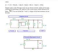
Es = 1 V, Rs = 50 N, Br.= 1 kN, Rj=5 kQ, ß = 100, Ro =2 kN, R1 = 100 2
Element values of the Thevenin circuit are not chosen correctly, which can be easily
confirmed by performing a DC analysis of the circuits (press toolbar Interactive DC
button oc
You can see that the V2 and V2e voltages on the load resistances are not
the same.
Original circuit
Rs 50
Rf 5k
Blb
V2
Es 1
RL 100
Source
Transistor
Load
Thevenin Equivalent circuit
RE? 2k
V2e
EE?
RL 100
Bre 1k
Ro 2k
Expert Solution
This question has been solved!
Explore an expertly crafted, step-by-step solution for a thorough understanding of key concepts.
Step by stepSolved in 3 steps with 4 images

Knowledge Booster
Similar questions
- To what extent does today's sophisticated technology make morals irrelevant?arrow_forwardHow should society begin to prepare for inevitability of Artificial Intelligence entering our daily lives?arrow_forwardCould you perhaps elaborate on what you mean by the term "principle of non-repudiation"? Thank you for your time.arrow_forward
- Suppose you are using a search algorithm to solve the 15-puzzle problem (i.e., the 4x4 version of the sliding-block puzzle we discussed in class). What are the benefits and drawbacks of using a depth first search? What are the benefits and drawbacks of using a breadth first search?arrow_forwardbecause, despite the fact that we may not be able to comprehend them, they may assist us discover answers to difficultiesarrow_forwardWhat is the "Principle of Non-Repudiation" according to you?arrow_forward
- In the context of computer science, please explain why it is possible for an individual's constitutionally protected right to free speech to come into conflict with the ownership of a trademark. How can these seemingly opposing points of view be reconciled so that they may be in peace with one another?arrow_forwardCan computers help decide sentences for criminals? If so, who should program the computer? What would Nils Christie say about using computers in this way? Note: I encourage you to interpret "computer" to mean all forms of artificial intelligence, including machine-learning. Do not limit yourself to current technology. I am asking whether we should do it, not whether computers are capable of it.arrow_forwardPlease help step by step with explanation for Program R (CS) with a final code for understanding thank you.arrow_forward
- What details on the philosopher Tollman can you provide?arrow_forwardExplain how the Constitutional right to free expression may come into conflict with the right to exclusive use of a trademark in the context of computer science. How can we ever reconcile these apparently irreconcilable differences?arrow_forwardWhat is the "Principle of Non-Repudiation" according to you?arrow_forward
arrow_back_ios
SEE MORE QUESTIONS
arrow_forward_ios
Recommended textbooks for you
 Computer Networking: A Top-Down Approach (7th Edi...Computer EngineeringISBN:9780133594140Author:James Kurose, Keith RossPublisher:PEARSON
 Computer Organization and Design MIPS Edition, Fi...Computer EngineeringISBN:9780124077263Author:David A. Patterson, John L. HennessyPublisher:Elsevier Science
 Network+ Guide to Networks (MindTap Course List)Computer EngineeringISBN:9781337569330Author:Jill West, Tamara Dean, Jean AndrewsPublisher:Cengage Learning
 Concepts of Database ManagementComputer EngineeringISBN:9781337093422Author:Joy L. Starks, Philip J. Pratt, Mary Z. LastPublisher:Cengage Learning
 Prelude to ProgrammingComputer EngineeringISBN:9780133750423Author:VENIT, StewartPublisher:Pearson Education
 Sc Business Data Communications and Networking, T...Computer EngineeringISBN:9781119368830Author:FITZGERALDPublisher:WILEY

Computer Networking: A Top-Down Approach (7th Edi...
Computer Engineering
ISBN:9780133594140
Author:James Kurose, Keith Ross
Publisher:PEARSON

Computer Organization and Design MIPS Edition, Fi...
Computer Engineering
ISBN:9780124077263
Author:David A. Patterson, John L. Hennessy
Publisher:Elsevier Science

Network+ Guide to Networks (MindTap Course List)
Computer Engineering
ISBN:9781337569330
Author:Jill West, Tamara Dean, Jean Andrews
Publisher:Cengage Learning

Concepts of Database Management
Computer Engineering
ISBN:9781337093422
Author:Joy L. Starks, Philip J. Pratt, Mary Z. Last
Publisher:Cengage Learning

Prelude to Programming
Computer Engineering
ISBN:9780133750423
Author:VENIT, Stewart
Publisher:Pearson Education

Sc Business Data Communications and Networking, T...
Computer Engineering
ISBN:9781119368830
Author:FITZGERALD
Publisher:WILEY