Power System Analysis and Design (MindTap Course List)
6th Edition
ISBN: 9781305632134
Author: J. Duncan Glover, Thomas Overbye, Mulukutla S. Sarma
Publisher: Cengage Learning
expand_more
expand_more
format_list_bulleted
Question
Please answer in typing format

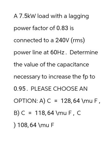
Transcribed Image Text:A 7.5kW load with a lagging
power factor of 0.83 is
connected to a 240V (rms)
power line at 60Hz. Determine
the value of the capacitance
necessary to increase the fp to
0.95. PLEASE CHOOSE AN
OPTION: A) C = 128,64 \mu F,
B) C = 118,64 \mu F, C
) 108, 64 \mu F
Expert Solution
This question has been solved!
Explore an expertly crafted, step-by-step solution for a thorough understanding of key concepts.
Step by stepSolved in 2 steps with 2 images

Knowledge Booster
Similar questions
- The rms value of v(t)=Vmaxcos(t+) is given by a. Vmax b. Vmax/2 c. 2Vmax d. 2Vmaxarrow_forwardAn industrial load consisting of a bank of induction motors consumes 50 kW at a power factor of 0.8 lagging from a 220-V,60-Hz, single-phase source. By placing a bank of capacitors in parallel with the load, the resultant power factor is to be raised to 0.95 lagging. Find the net capacitance of the capacitor bank in F that is required.arrow_forwardShown in the figure below is an "RC" circuit drive by an AC power source. The AC power source has an RMS voltage of Vps (RMS) = 11.58 Volts and is running at a frequency of f = 1.326e+04 Hz. resistor has a resistance of R = 3750 2 and the capacitor has an capacitance of C = 3.17e-09 Farads. Vps R ww Write the FORMULA for the total impedance of the circuit Ztot = Write the FORMULA for the phase of the total impedance of the circuit tot = Determine the numerical value of Ztot = Determine the numerical value of Pztot= Determine the current through the circuit: • I(PEAK) = • I(RMS) = Determine the voltage across the resistor: Amps Amps S2 C degreesarrow_forward
- 2.14 The current waveforms of la capocitov are avesage peak cursend *atings of 1, =500 A of shown in Fiquse Determine square (rms), and capacitor. Assume, The root mean half sine -wave t = loo us -300 AS t3 Soo Ns f, -250HZ T2 200arrow_forwardShown in the figure below is an "RL" circuit drive by an AC power source. The AC power source has an RMS voltage of Vps (RMS) = 9.84 Volts and is running at a frequency of f = 8.585e+04 Hz. The resistor has a resistance of R = 2170 and the inductor has an inductance of L = 3.54e-03 Henries. Vps R ww Write the FORMULA for the total impedance of the circuit Ztot = Determine the numerical value of Ztot = 2890.5 Determine the numerical value of $z= = 41 Determine the current through the circuit: • I(PEAK) = 4.81E-3 • I(RMS) = 3.404E-3 Determine the voltage across the resistor: • VR(PEAK) = 7.387 • VR(RMS) = 5.22 ✔✔ Amps ✔Amps Write the FORMULA for the phase of the total impedance of the circuit z... = | tan-1 2701 R x Volts X Volts Determine the voltage across the inductor: • VL(PEAK) = 9.184 • VL(RMS) = 6.49 ✔ Volts Volts L R²+ WL- ✔ degrees 2 If a second circuit were connected in parallel with the inductor, this circuit would be considered as: O a low-pass filter O a capacitive switcher…arrow_forwardPlease answer alll subparts for like either dislike...arrow_forward
- . Determine the capacitance value that, when placed in parallel with this load, would produce a unity power factor. Assume that the source is 230 V at 60 Hz. The Q shown is a positive Inductive reactive power, which would have to be “offset” by the same value of Reactive Capacitance Power.arrow_forwardIf, in one (360 degrees), all of the instantaneous power falls under positive loops (no negativeloops), the load must be:a. A resistorb. An inductor or capacitorExplain:arrow_forwardSuppose I have two peak phasor voltages, V, = 100245° and V, = 75Z-60°. Circle Your Choices: I. The frequencies associated with the phasors are (0 Hz, 60 Hz, 50 Hz, Unknown). II. The rms value of the first phasor is (100, 70.7, 141, 200) volts. III. If you want to add these two phasors, the frequencies must be (60 Hz, 50 Hz, The same, Integer multiples of a given frequency.)arrow_forward
- For the phasor diagram in figure 6 express the voltages in sinusoids for a period of 5ms. Im Re )e,=45° e,=20 Vz=10 V2=8 Figure 7 a. Va(t)=. b. V2(t)=. c. What is the rms voltage of V1 = d. What is the rms voltage of V2=_ e. What is the frequency in Hz = f. What is the angular frequency =. In terms of lagging and leading what is the exact phase relationship between V, (t) and V2(t) g.arrow_forwardcan you doing this with detail explaination..thank you!arrow_forwardchoose the correct option for ac circuitarrow_forward
arrow_back_ios
SEE MORE QUESTIONS
arrow_forward_ios
Recommended textbooks for you
 Power System Analysis and Design (MindTap Course ...Electrical EngineeringISBN:9781305632134Author:J. Duncan Glover, Thomas Overbye, Mulukutla S. SarmaPublisher:Cengage Learning

Power System Analysis and Design (MindTap Course ...
Electrical Engineering
ISBN:9781305632134
Author:J. Duncan Glover, Thomas Overbye, Mulukutla S. Sarma
Publisher:Cengage Learning