Introductory Circuit Analysis (13th Edition)
13th Edition
ISBN: 9780133923605
Author: Robert L. Boylestad
Publisher: PEARSON
expand_more
expand_more
format_list_bulleted
Question

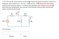
Transcribed Image Text:7.11.1 For the RL circuit shown in the image below, the switch has been closed for a
long time, and it opens at t= 0. If R1 = 6 S2 and R2 = 4 S2, determine the energy
stored in the inductor when t = 0. Please pay attention: the numbers may change
since they are randomized. Your answer must include 3 places after the decimal
point, and the proper Sl unit.
t = 0
R1
4 H
ell
24 V(+
4Ω
R2
Your Answer:
Answer
units

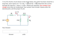
Transcribed Image Text:7.11.2 For the RL circuit shown in the image below, the switch has been closed for a
long time, and it opens at t = 0. If R1 = 1 2 and R2 = 3 2, determine the current
through the inductor, i, when t = 0.04 s. Please pay attention: the numbers may
change since they are randomized. Your answer must include 3 places after the
decimal point, and the proper SI unit.
t = 0
R,
4 H
ll
24 V(+
4 2
R2
Your Answer:
Answer
units
Expert Solution
This question has been solved!
Explore an expertly crafted, step-by-step solution for a thorough understanding of key concepts.
Step by stepSolved in 2 steps with 1 images

Knowledge Booster
Learn more about
Need a deep-dive on the concept behind this application? Look no further. Learn more about this topic, electrical-engineering and related others by exploring similar questions and additional content below.Similar questions
- A battery, resistor, capacitor and switch are connected in series to form an RC circuit as shown below. The switch is closed at time t=0 s. Which of the following statements regarding the circuit is correct? Switch S t M R C + 1 O The potential difference across the capacitor is always greater than the potential difference across the resistor O The potential difference across the resistor is always greater than the potential difference across the capacitor. O Once the capacitor is essentially fully charged, there is no appreciable current in the circuit. O The capacitor charges to its maximum value in one time constant and the current is zero at that time. O The potential difference across the resistor and the potential difference across the capacitor are always equal.arrow_forward4) Consider the circuit shown in the Figure, where C₁ = 6.00 µF, C₂ = 3.00 μF, and AV=20.0 V. Capacitor C₁ is first charged by the closing of switch S₁. Switch S₁ is then opened, and the charged capacitor is connected to the uncharged capacitor by the closing of S₂. Calculate the final charge on C₂. A) 120 µC B) 80 µC C) 40 μC D) 60 μC E) 20 μC AI LI 5arrow_forward7 Use Kirchhoff's loop rule to R2 write two equations describing this cir- cuit (assuming the switch is closed). You may use any of the symbols in the fig- ure and any currents or capacitor charges that you define. opyright C1 C2arrow_forward
- -In the circuit shown on the right the switch S has been open for a long time. What is the current flow through the inductor (0, 2 to 1, or 1 to 2) ? -In the circuit shown on the right the switch S has been open for a long time. At the instant the switch S is closed, the current flow through the inductor is (0, 1 to 2, or 2 to 1)? -In the circuit shown on the right the switch S has been open for a long time. The current flow through the inductor is (increasing, steady, or decreasing)? -In the circuit shown on the right the switch S has been open for a long time. Immediately after the switch S is closed, the current flow through the inductor is (increasing, steady, or deacreasing)? -In the circuit shown on the right the switch S has been closed for a long time. The current flow through the inductor is (1 to 2, 2 to 1, or 0)? -In the circuit shown on the right the switch S has been closed for a long time. At the instant the switch S is opened, the current flow through the inductor is (1…arrow_forwardHello I need help with part A and part B and part C is there any possible way that you could help me with those three parts and can you label them as wellarrow_forwardAll capacitors were initially discharged.at t = 0, S1 is placed at position 1 and S2 is closed.At t = 15 ms, S1 is placed at position 2 and S2 is kept closed. At t = 25 ms, S1 is kept at position 2 and S2 is opened.after 25 ms, the voltage vT will Question options: increase until it reaches the battery voltage at steady state exponentially decay to zero stay constant be a sine wavearrow_forward
arrow_back_ios
arrow_forward_ios
Recommended textbooks for you
 Introductory Circuit Analysis (13th Edition)Electrical EngineeringISBN:9780133923605Author:Robert L. BoylestadPublisher:PEARSON
 Delmar's Standard Textbook Of ElectricityElectrical EngineeringISBN:9781337900348Author:Stephen L. HermanPublisher:Cengage Learning
 Programmable Logic ControllersElectrical EngineeringISBN:9780073373843Author:Frank D. PetruzellaPublisher:McGraw-Hill Education
 Fundamentals of Electric CircuitsElectrical EngineeringISBN:9780078028229Author:Charles K Alexander, Matthew SadikuPublisher:McGraw-Hill Education
 Electric Circuits. (11th Edition)Electrical EngineeringISBN:9780134746968Author:James W. Nilsson, Susan RiedelPublisher:PEARSON
 Engineering ElectromagneticsElectrical EngineeringISBN:9780078028151Author:Hayt, William H. (william Hart), Jr, BUCK, John A.Publisher:Mcgraw-hill Education,

Introductory Circuit Analysis (13th Edition)
Electrical Engineering
ISBN:9780133923605
Author:Robert L. Boylestad
Publisher:PEARSON

Delmar's Standard Textbook Of Electricity
Electrical Engineering
ISBN:9781337900348
Author:Stephen L. Herman
Publisher:Cengage Learning

Programmable Logic Controllers
Electrical Engineering
ISBN:9780073373843
Author:Frank D. Petruzella
Publisher:McGraw-Hill Education

Fundamentals of Electric Circuits
Electrical Engineering
ISBN:9780078028229
Author:Charles K Alexander, Matthew Sadiku
Publisher:McGraw-Hill Education

Electric Circuits. (11th Edition)
Electrical Engineering
ISBN:9780134746968
Author:James W. Nilsson, Susan Riedel
Publisher:PEARSON

Engineering Electromagnetics
Electrical Engineering
ISBN:9780078028151
Author:Hayt, William H. (william Hart), Jr, BUCK, John A.
Publisher:Mcgraw-hill Education,