Introductory Circuit Analysis (13th Edition)
13th Edition
ISBN: 9780133923605
Author: Robert L. Boylestad
Publisher: PEARSON
expand_more
expand_more
format_list_bulleted
Question

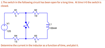
Transcribed Image Text:1.The switch in the following circuit has been open for a long time. At time t=0 the switch is
closed.
+
V1
120
R1
5
R4
R2
10
R3
L1
100mH
15
5
Determine the current in the inductor as a function of time, and plot it.
Expert Solution
This question has been solved!
Explore an expertly crafted, step-by-step solution for a thorough understanding of key concepts.
This is a popular solution
Step 1: Summarize the data.
VIEW Step 2: Determine the initial current through the inductor.
VIEW Step 3: Determine the time constant for t > 0.
VIEW Step 4: Determine the expression of the current through the inductor.
VIEW Step 5: Sketch the plot of the current through the inductor.
VIEW Solution
VIEW Trending nowThis is a popular solution!
Step by stepSolved in 6 steps with 8 images

Knowledge Booster
Similar questions
- I need the answer as soon as possiblearrow_forwardQuestion 4 Figure 7 shows a recorded current waveform i(@t) from a converter. The current is related to (@t) during each cycle and alternates between 0 and +IL. The current waveform varies with time at constant frequency. i(ot +IL ot -T -Tt/2 T/2 3t/2 Figure 7 a) Determine the expression that describes the waveform i(@t) shown in Figure 7 as a function of ot. 1 b) Calculate the average value: a, . c) Identify all symmetries of the waveform i(ot) Figure 7.arrow_forwardI need the answer as soon as possiblearrow_forward
- Needs Complete solution with 100 % accuracy.arrow_forwardLecture Review Assignment Draw a circuit with only one resistor and capacitor that is equivalent to this circuit. What is the time constant of this RC circuit? R₁ www After a long time of charging, what is the charge on the capacitor 1 and current in resistor 1? V S C3 V = 6.0V R₁ = 250 25Ω R₂ = 330 33N R₂ C₁ C₂ C₁ C₁ = 12µF C₂ = 23µF C3 C3 = 46µFarrow_forwardHello I need help with part A and part B and part C is there any possible way that you could help me with those three parts and can you label them as wellarrow_forward
- Q2/ For the network shown in figure (Q2), the switch has been open for a long time before closing at t=0. Determine an expression for the inductor (L=20mH) current İL(t) for t20. 300 L 36V iL (2othH 5oonF 12 ISA losrarrow_forwardA charged capacitor of C-46.0 µF is connected to a resistor of R-2.8 M2 as shown in the figure. The switch S is closed at time 1-0. Find the time (in seconde) sakes the current to fall to 0.25 of its initial value. R wwwarrow_forwardAn alternating current E(t)=120sin(12t) has been running through a simple circuit for a long time. The circuit has an inductance of L= 0.44 henrys, a resistor of R=7 ohms, and a capacitor of capacitance C= 0.032 farads.What is the amplitude of the current I?arrow_forward
- Hi im struggling to understand how you would sketch DC component Va and AC component va for the following questions. Could you show me how on both questions so i understand how to do it on different scenarios. thank you.Also is there like a universal formula i can use as every graph is not the same. Also can u show how to identify the period of each graph.arrow_forwardIn order to get the step 4 the full yellow paper will be the guide to find the step 4. STEP 1: Current Loops STEP 2: Remove Integrals STEP 3: Simplify STEP 4: ? Note: THE YELLOW FULL PAPER HAVE A DIFFERENT GIVEN YOU WILL JUST USE THIS AS A GUIDE OR REFERENCES HOW TO SOLVE THE STEP 4:arrow_forwardplease choose one of these snswers thank you thevsteady equilibrium current that exists in the inductor is nearly 2.5A 2.27A 1.36A 0.91A In the given circuit, the inductor (L-5 H) and a 50-V battery of negligible resistance are connected with resistors R 10 W and R2 30 w, and Rg 20 Ww as shown. The switch was closed at t 0 and kept closed for a long time until a steady equilibrium current existed.arrow_forward
arrow_back_ios
arrow_forward_ios
Recommended textbooks for you
 Introductory Circuit Analysis (13th Edition)Electrical EngineeringISBN:9780133923605Author:Robert L. BoylestadPublisher:PEARSON
 Delmar's Standard Textbook Of ElectricityElectrical EngineeringISBN:9781337900348Author:Stephen L. HermanPublisher:Cengage Learning
 Programmable Logic ControllersElectrical EngineeringISBN:9780073373843Author:Frank D. PetruzellaPublisher:McGraw-Hill Education
 Fundamentals of Electric CircuitsElectrical EngineeringISBN:9780078028229Author:Charles K Alexander, Matthew SadikuPublisher:McGraw-Hill Education
 Electric Circuits. (11th Edition)Electrical EngineeringISBN:9780134746968Author:James W. Nilsson, Susan RiedelPublisher:PEARSON
 Engineering ElectromagneticsElectrical EngineeringISBN:9780078028151Author:Hayt, William H. (william Hart), Jr, BUCK, John A.Publisher:Mcgraw-hill Education,

Introductory Circuit Analysis (13th Edition)
Electrical Engineering
ISBN:9780133923605
Author:Robert L. Boylestad
Publisher:PEARSON

Delmar's Standard Textbook Of Electricity
Electrical Engineering
ISBN:9781337900348
Author:Stephen L. Herman
Publisher:Cengage Learning

Programmable Logic Controllers
Electrical Engineering
ISBN:9780073373843
Author:Frank D. Petruzella
Publisher:McGraw-Hill Education

Fundamentals of Electric Circuits
Electrical Engineering
ISBN:9780078028229
Author:Charles K Alexander, Matthew Sadiku
Publisher:McGraw-Hill Education

Electric Circuits. (11th Edition)
Electrical Engineering
ISBN:9780134746968
Author:James W. Nilsson, Susan Riedel
Publisher:PEARSON

Engineering Electromagnetics
Electrical Engineering
ISBN:9780078028151
Author:Hayt, William H. (william Hart), Jr, BUCK, John A.
Publisher:Mcgraw-hill Education,