Introductory Circuit Analysis (13th Edition)
13th Edition
ISBN: 9780133923605
Author: Robert L. Boylestad
Publisher: PEARSON
expand_more
expand_more
format_list_bulleted
Question
Please answer in typing format

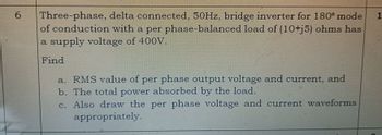
Transcribed Image Text:6
Three-phase, delta connected, 50Hz, bridge inverter for 180° mode 1
of conduction with a per phase-balanced load of (10+j5) ohms has
a supply voltage of 400V.
Find
a. RMS value of per phase output voltage and current, and
b. The total power absorbed by the load.
c. Also draw the per phase voltage and current waveforms
appropriately.
Expert Solution
This question has been solved!
Explore an expertly crafted, step-by-step solution for a thorough understanding of key concepts.
Step by stepSolved in 2 steps with 3 images

Knowledge Booster
Similar questions
- I need to solve it quicklyarrow_forwardsingle phase half bridge inverter has load r=2ohm and dc souuce voltage vs/2=115v . calculate THD and HFarrow_forwardQ2. A single -phase full-bridge inverter is operated from a 48 V battery and is supplying power to a pure resistive load of 10 ohm. Calculate Fundamental component of the output voltage waveform First five harmonics of the output voltage waveform RMS value of the output voltage and output fundamental power i. ii. ii. Rating of SCR Verify the RMS value determined by harmonic summation method is nearly equal to the iv. v. value determined by integration methodarrow_forward
- The following three phase inverter in Figure 1 below is supplied by a DC voltage of VDc = 1000V and connected to the star connection of resistive load, R=60n. The load frequency is 50HZ. Assume that three switches are conducted at each interval. State the sequence number of conducting transistor for each interval and illustrate the equivalent circuit connection of load for each interval. Based on the equivalent circuit connection of load, determine the value of line voltage VRy and value of phase voltage VRN. Provide your answers in Table 1. (C3,CLO1) Duration Switch VRN VyN VRY Mode 0°-60° 60°-120° 120°-180° 180°-240° 240°-300° 300°-360° Table 1arrow_forwardQ2 (a) A single-phase full-bridge square-wave voltage source inverter has R and L load of 25 n and 15 mH, respectively and the load is connected in parallel. The inverter output frequency is 50 Hz while the transistor switching scheme is complementary bipolar (i) Define the expression of the RMS output voltage at the fundamental frequency. (ii) If the fundamental output voltage is 240 Vrms, identify the required DC input voltage for the inverter. (iii) Calculate the instantaneous load current by considering until the 7th harmonics number. (iv) Sketch the harmonic spectrum for output current. 2arrow_forwardIn motor control of train, IGBT control AC motor save more energy than GTO due to less switching loss. State THREE more reasons why IGBT use in motor control has many advantages over GTO. If one of the freewheeling diode in your single phase inverter in above settings has reverse recovery failure. Describe what would happen to the circuit.arrow_forward
- Thanks for the help This is about the integrated fabrication process for microelectronic devices for a bipolar n-p-n transistor; . Please work out the fabrication process flow. In each step of fabrication process, please illustrate the cross-section of the structure and indicate the material of each layer, the patterning of each layer and the process used.arrow_forward(i) Draw the circuit diagram of the single phase full wave controlled rectifier (RL load) with center-tapped transformer and compare its performance with uncontrolled rectifier operation. (ii) A single phase fully controlled bridge rectifier circuit has DC output voltage 165 V for an AC supply voltage of 230 V rms. Find the firing angle delay of the circuit for the following cases (a) Converter mode (b) Inverter mode Converter mode delay angle Inverter mode delay anglearrow_forward
arrow_back_ios
arrow_forward_ios
Recommended textbooks for you
 Introductory Circuit Analysis (13th Edition)Electrical EngineeringISBN:9780133923605Author:Robert L. BoylestadPublisher:PEARSON
 Delmar's Standard Textbook Of ElectricityElectrical EngineeringISBN:9781337900348Author:Stephen L. HermanPublisher:Cengage Learning
 Programmable Logic ControllersElectrical EngineeringISBN:9780073373843Author:Frank D. PetruzellaPublisher:McGraw-Hill Education
 Fundamentals of Electric CircuitsElectrical EngineeringISBN:9780078028229Author:Charles K Alexander, Matthew SadikuPublisher:McGraw-Hill Education
 Electric Circuits. (11th Edition)Electrical EngineeringISBN:9780134746968Author:James W. Nilsson, Susan RiedelPublisher:PEARSON
 Engineering ElectromagneticsElectrical EngineeringISBN:9780078028151Author:Hayt, William H. (william Hart), Jr, BUCK, John A.Publisher:Mcgraw-hill Education,

Introductory Circuit Analysis (13th Edition)
Electrical Engineering
ISBN:9780133923605
Author:Robert L. Boylestad
Publisher:PEARSON

Delmar's Standard Textbook Of Electricity
Electrical Engineering
ISBN:9781337900348
Author:Stephen L. Herman
Publisher:Cengage Learning

Programmable Logic Controllers
Electrical Engineering
ISBN:9780073373843
Author:Frank D. Petruzella
Publisher:McGraw-Hill Education

Fundamentals of Electric Circuits
Electrical Engineering
ISBN:9780078028229
Author:Charles K Alexander, Matthew Sadiku
Publisher:McGraw-Hill Education

Electric Circuits. (11th Edition)
Electrical Engineering
ISBN:9780134746968
Author:James W. Nilsson, Susan Riedel
Publisher:PEARSON

Engineering Electromagnetics
Electrical Engineering
ISBN:9780078028151
Author:Hayt, William H. (william Hart), Jr, BUCK, John A.
Publisher:Mcgraw-hill Education,