Electric Motor Control
10th Edition
ISBN: 9781133702818
Author: Herman
Publisher: CENGAGE L
expand_more
expand_more
format_list_bulleted
Question

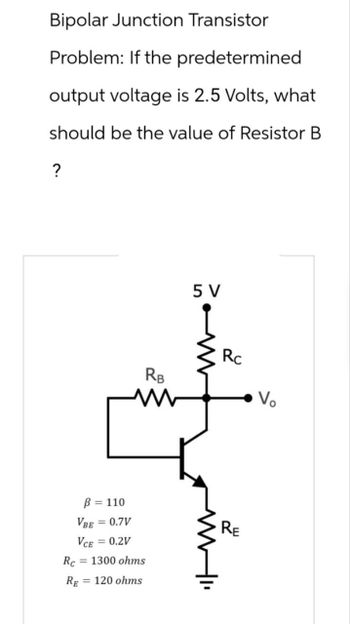
Transcribed Image Text:Bipolar Junction Transistor
Problem: If the predetermined
output voltage is 2.5 Volts, what
should be the value of Resistor B
?
5 V
RB
www
Rc
Vo
Rc
ẞ = 110
VBE = 0.7V
VCE = 0.2V
= 1300 ohms
RE 120 ohms
RE
Expert Solution
This question has been solved!
Explore an expertly crafted, step-by-step solution for a thorough understanding of key concepts.
This is a popular solution
Trending nowThis is a popular solution!
Step by stepSolved in 2 steps with 3 images

Knowledge Booster
Similar questions
- Explain the concept of power semiconductor devices such as Insulated Gate Bipolar Transistors (IGBTs) and Thyristors. How do these devices enable efficient power control and switching in high-power applications?arrow_forward4. For the circuit shown in Figure, determine IC and VCB. Assume the transistor to be of Germanium.arrow_forwardA PWM signal changes with a voltage of -15 and 15 volts while it is desirable to produce an effective (average) voltage of the PWM signal of 9 volts. The duty cycle that must be generated isarrow_forward
- A 4.7 zener diode is connected to the base resistor. The left side of the resistor sits at about 12V. The right side of the biasing resistor is connected to the Zener and npn transistor. The Zener bias is 5mA. The base current needed is 80uA. What is the appropriate resistor for this circuit? (In kohms) Iarrow_forwardHow do bipolar junction transistors (forward active) apply to engineering? List two examples.arrow_forwardSet up a midpoint bias for a JFET with IDSS = 14 mA and VGS(off) = -10 V. Use a 24 V dc source as the supply voltage. Show the circuit and resistor values. Indicate the value of ID. Indicate the value of VGS. Indicate the value of VDS.arrow_forward
- Kindly provide a CLEAR and COMPLETE solution.arrow_forwardQ3) A. A step down de chopper is connected to an R=52 and L=10 mH. The de supply voltage is 100 V. The chopper is switching at a frequency of 1 kHz with a duty cycle of 50%. Determine the load current, lo and the peak to peak ripple current as an absolute value and as percentage of de value.arrow_forwardQuestion: 8. With the emitter bias shown, a reasonable assumption for troubleshooting work is that the VcC a. base voltage =+1 V +15 V b. emitter voltage = +5 V RC 3.9 k2 c. emitter voltage =-1 V d. collector voltage = Vcc RB 68 kQ %3D RE 7.5 kQ VEE -15 Varrow_forward
- IDSS=8mA , VP =-4VTo help plot the DC load line VGS=VG-IDRSa)Attach a Plot of JFET Characteristic Curve as shown in Figureb)What is the approximate VGSQ?c)What is the approximate IDQ in mA?d)Determine source voltage VS.e)Calculate the drain voltage VD.f)Calculate the drain-to-source voltage VDS.arrow_forwardIf a sinusoidal voltage is applied to the base of a biased npn transistor and the resulting sinusoidal collector voltage is cut to near zero volts, what is the state of the transistor? Please select one: a. answers B and C b. interrupted drive c. answers A and C d. forced into nonlinear operation e. drifting into saturationarrow_forward
arrow_back_ios
arrow_forward_ios
Recommended textbooks for you
