
Power System Analysis and Design (MindTap Course List)
6th Edition
ISBN: 9781305632134
Author: J. Duncan Glover, Thomas Overbye, Mulukutla S. Sarma
Publisher: Cengage Learning
expand_more
expand_more
format_list_bulleted
Related questions
Question
Please solve a to c handwritten detailed step by step solution thank you
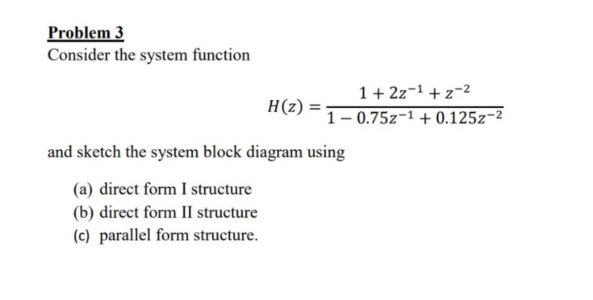

Transcribed Image Text:Problem 3
Consider the system function
H(z)
=
1+2z 1 + z-2
1 -0.75z-1 + 0.125z-2
and sketch the system block diagram using
(a) direct form I structure
(b) direct form II structure
(c) parallel form structure.
Expert Solution
This question has been solved!
Explore an expertly crafted, step-by-step solution for a thorough understanding of key concepts.

Step by stepSolved in 2 steps with 3 images

Knowledge Booster

Similar questions
- What impedance vector - j25 represents:A. A pure resistance. C. A pure capacitance.B. A pure inductance. D. An inductance combined with a resistance.arrow_forward(a) Transform v(t)=75cos(377t15) to phasor form. Comment on whether =377 appears in your answer. (b) Transform V=5010 to instantaneous form. Assume that =377. (c) Add the two sinusoidal functions a(t) and b(t) of the same frequency given as follows: a(t)=A2cos(t+) and b(t)=B2cos(t+). Use phasor methods and obtain the resultant c(t). Does the resultant have the same frequency?arrow_forwardWhat is the calculation process in Zmarrow_forward
- An inductor, a capacitor, and a resistor are connected in parallel with a function generator. The inductor draws 100mA RMS, the capacitor draws 150mA RMS, and the resistor draws 200mA RMS. Find the magnitude of the total current.arrow_forwardhetee to the series ciecuit Given: RT series Ciecuit t=\.5KR R1=500 below and I =50MA %3D Find Rz, VT, VieVz oVí farrow_forwardfor the given circuit find p & q for the load as shownarrow_forward
- Below is a circuit diagram. Create a set of equations by using mesh analysis. The value of Rnsid is equal to 625. Express the final answer as rectangular coordinates.arrow_forwardл-pad attenuators are commonly used in radio frequency and microwave transmission lines and can be balanced or unbalanced designs. The unbalanced attenuator shown in figure 2 below is supplied by two DC sources, one at each end. You have been asked to calculate the current through R3 and R5 using the Superposition Theorem and the appropriate set of values from table 1 below. Show step by step working out. 5 R1 R2 50V 5 R5 R3 ㅋ Fig 2 7 R4 4 R6 30Varrow_forwardThe circuit shown in figure EM1-1 shows an AC voltage source VAC connected in series with a load that has • resistance R=280 Ohms, inductance L=1.1mH, and • capacitance C=4.7mF. Calculate values of, and select the apporpriate answer from the list from the list below for • the frequency, fres (in Hz) of the AC source that results in resonance in the load and the impedance, Zres (in Ohms) of the load at this frequency. ● Resonant Frequency, fres= ✓ Hz Impedance of the Load at Resonance, Zres= R 280 Ω ✓ Ohms V. AC L 4.7 mF 1.1 mH Figure EM1-1 Downloadable imagearrow_forward
- USE STORED VALUES AND ROUND OFF TO FOUR DECIMAL PLACES. PLEASE SHOW COMPLETE SOLUTION.arrow_forwardPlease solvearrow_forward3&page%3D1 American Uni. Girne American Uni.. O portal.gaueng.org My Profile - Zoom Dashboard My Courses This course Find the Norton equivalent of the circuit 60 30 40V ,50 202 A BI E E E E ere to searcharrow_forward
arrow_back_ios
SEE MORE QUESTIONS
arrow_forward_ios
Recommended textbooks for you
- Power System Analysis and Design (MindTap Course ...Electrical EngineeringISBN:9781305632134Author:J. Duncan Glover, Thomas Overbye, Mulukutla S. SarmaPublisher:Cengage Learning
Power System Analysis and Design (MindTap Course ...
Electrical Engineering
ISBN:9781305632134
Author:J. Duncan Glover, Thomas Overbye, Mulukutla S. Sarma
Publisher:Cengage Learning