
Elements Of Electromagnetics
7th Edition
ISBN: 9780190698614
Author: Sadiku, Matthew N. O.
Publisher: Oxford University Press
expand_more
expand_more
format_list_bulleted
Related questions
Question
thumb_up100%
Please show all solving step especially when g=32.2

Transcribed Image Text:5:41 PM
G
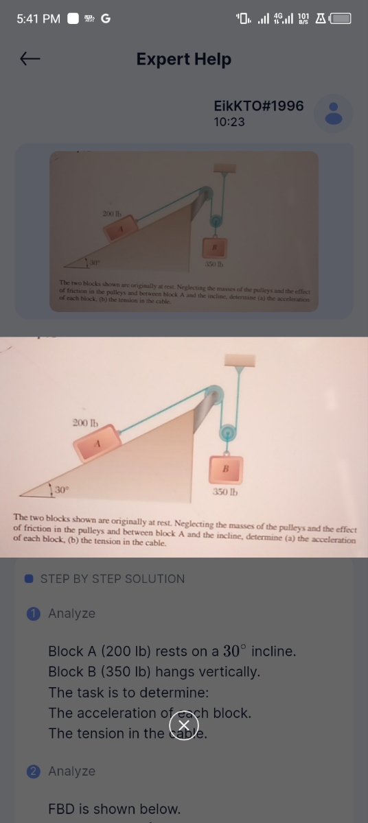
30°
200 lb
Expert Help
'AC
EikKTO#1996
10:23
350 lb
The two blocks shown are originally at rest. Neglecting the masses of the pulleys and the effect
of friction in the pulleys and between block A and the incline, determine (a) the acceleration
of each block, (b) the tension in the cable.
30°
200 lb
B
350 lb
The two blocks shown are originally at rest. Neglecting the masses of the pulleys and the effect
of friction in the pulleys and between block A and the incline, determine (a) the acceleration
of each block, (b) the tension in the cable.
STEP BY STEP SOLUTION
Analyze
Block A (200 lb) rests on a 30° incline.
Block B (350 lb) hangs vertically.
The task is to determine:
The acceleration of each block.
The tension in the cable.
Analyze
FBD is shown below.
Expert Solution
This question has been solved!
Explore an expertly crafted, step-by-step solution for a thorough understanding of key concepts.

Step by stepSolved in 2 steps with 1 images

Knowledge Booster

Similar questions
- A 75-kg block is attached to a cable. The cable is then attached to a rotating assembly with a mass moment of inertia of 18 kg-m^2. The bearing friction applied at the rotating assembly equivalent to a couple of 45 N-m CCW. The block's downward speed is initially at 2 m/s. 0.3 m 75 kg m 1. Which of the following does positive work on the system? 2. Which of the following is closest to the work done by the bearing friction after the rotating assembly has rotated 1.5 radians CW? 3. Which of the following is closest to the work done by the weight of the 75-kg block after the rotating assembly has rotated 1.5 radians CW? 4. Which of the following is closest to the total work done by the system after the rotating assembly has rotated 1.5 radians CW? 5. Which is following is closest to the speed of the 75-kg block after the rotating assembly rotated 1.5 rad CW?arrow_forwardA box of mass 20 kg moves up a rough plane which is inclined to the horizontal at 25.0o .It is pulled by a horizontal force F of magnitude 250N . The Coefficient of kinetic friction between thr box and the plane is 0.300 a) if the box travels 3.80 m along the plane determine i. The work done on the box by the force F ii. The work done on the box by gravitational force iii. The work done on the box by reaction force and the work done on the box by frictional force v. total work done on the box b) If the speed of box is zero at bottom plane ,calculate it speed when it travellef 3.80 m (given g=9.81m/s2)arrow_forwardA light spring with force constant 3.80 N/m is compressed by 7.60 cm as it is held between a 0.300-kg block on the left and a 0.600-kg block on the right, both resting on a horizontal surface. The spring exerts a force on each block, tending to push the blocks apart. The blocks are simultaneously released from rest. Find the acceleration with which each block starts to move, given that the coefficient of kinetic friction between each block and the surface is 0, 0.072, and 0.434. (Let the coordinate system be positive to the right and negative to the left. Indicate the direction with the sign of your answer. Assume that the coefficient of static friction is the same as the coefficient of kinetic friction. If the block does not move, enter 0.)arrow_forward
- Please help in 3, 4, and 5arrow_forwardThe system shown below is released from rest and slider B moves to the right with the constant acceleration of aB = 4 m. Force P= 21 Newtons is always acting on slider B. Consider massless-frictionless pulleys and massless cable and mass of slider B is 2 kg. What is the magnitude of normal force developed between slider B and the rail in Newtons. Consider g =10 . marrow_forward4) This Atwood's machine includes two blocks connected by a cable, going over a pulley without slipping. Block 1 (30.0 kg) is connected to a spring (70.0 N/m), and slides on a horizontal surface with a coefficient of kinetic friction of 0.0100. Block 2 is 50.0 kg, and hangs vertically from the cable. The pulley is a disk with a radius of 0.500 m, and its moment of inertia about the center of mass is 10. 0 kg-m“. a) Draw the three free body diagrams, and write out Newton's 2nd Law for each. b) Derive the equation of motion (inhomogeneous 2nd order ODE) for this system. c) Use u-substitution to rewrite this as a homogeneous 2nd order ODE. d) Assume the position x as a function of time t is of the form x(t) = A cos (wt + p) I disk for undamped natural frequency w, phase angle P, and amplitude A. The initial conditions are: x(0) v(0) = -3. 00 m/s. Solve for the position of the mass as a function of time (you need to solve for w, 4, and A). = 2. 00 m and Mzarrow_forward
- Q5.) Wedge B is positioned above wedge A as shown. Each wedge has a mass of 12 kg. A linear elastic spring attached to wedge A has a spring constant of 3 kN/m and is currently compressed 0.06 meters from its unstretched length. The coefficient of static friction between the two wedges is 0.5 and the coefficient of static friction between wedge A and the ground is 0.35. A force of P is applied to the corner of wedge B at an angle 30°. Determine the minimum applied force that would cause motion to occur and specify how the system will move. k = 3 kN/m W A 20° B P 30°arrow_forwardQ5.) Wedge B is positioned above wedge A as shown. Each wedge has a mass of 12 kg. A linear elastic spring attached to wedge A has a spring constant of 3 kN/m and is currently compressed 0.06 meters from its unstretched length. The coefficient of static friction between the two wedges is 0.5 and the coefficient of static friction between wedge A and the ground is 0.35. A force of P is applied to the corner of wedge B at an angle 30°. Determine the minimum applied force that would cause motion to occur and specify how the system will move. k = 3 kN/m A B 20⁰ 30°arrow_forwardConsider the following diagram. m1320 kg and m2= 10 kg. The system is being pulled by an applied force of 200 N, directed 50 above the horizontal. The coefficient of kinetic friction between the block and the surface is u=0.2. 500 20kg m, 10 kg Coeficent of friction 4= 0.2 30 7) Calculate the acceleration of the system. * Your answer 8) Calculate the magnitude of the Tension on the rope. Your answerarrow_forward
- Block A is sliding down and pulling up both Block B and Block C. Find the accelerations of each body and the tension of rope if the coefficient of friction at Block A is 0.25 and at Block C is 0.35 A= 2000b B= 500 b C: 1000lb 314 Aarrow_forward2. Two blocks connected by a string passing over a pulley are on ramps inclined at 32 degrees and 25 degrees. The mass of block #1 is 1.8 kg and the mass of block #2 is 1.0 kg. Between block #1 and its ramp, the coefficients of static and kinetic friction are 0.15 and 0.10, respectively. There is no friction between block #2 and its ramp. The system is released from rest and the blocks move. The pulley is massless and frictionless, so you can ignore the pulley. b. C. d. 32° 25° Draw a free body diagram (FBD) for each block. Include all of the forces acting on the two blocks. Apply Newton's Second Law to each block to obtain an equation for the forces acting on each block in the x-direction and an equation for the forces acting on each block in the y-direction. Consider the information provided about this system. When the blocks are released from rest, what direction will the blocks move? Explain why? Calculate the acceleration of the blocks. Iarrow_forward7. A car whose brakes are locked skids to a stop 70 m from an initial velocity of 80 km/h. Find the coefficient of kinetic friction.arrow_forward
arrow_back_ios
SEE MORE QUESTIONS
arrow_forward_ios
Recommended textbooks for you
- Elements Of ElectromagneticsMechanical EngineeringISBN:9780190698614Author:Sadiku, Matthew N. O.Publisher:Oxford University Press
 Mechanics of Materials (10th Edition)Mechanical EngineeringISBN:9780134319650Author:Russell C. HibbelerPublisher:PEARSON
 Thermodynamics: An Engineering ApproachMechanical EngineeringISBN:9781259822674Author:Yunus A. Cengel Dr., Michael A. BolesPublisher:McGraw-Hill Education
  Control Systems EngineeringMechanical EngineeringISBN:9781118170519Author:Norman S. NisePublisher:WILEY
 Mechanics of Materials (MindTap Course List)Mechanical EngineeringISBN:9781337093347Author:Barry J. Goodno, James M. GerePublisher:Cengage Learning
 Engineering Mechanics: StaticsMechanical EngineeringISBN:9781118807330Author:James L. Meriam, L. G. Kraige, J. N. BoltonPublisher:WILEY
Elements Of Electromagnetics
Mechanical Engineering
ISBN:9780190698614
Author:Sadiku, Matthew N. O.
Publisher:Oxford University Press
Mechanics of Materials (10th Edition)
Mechanical Engineering
ISBN:9780134319650
Author:Russell C. Hibbeler
Publisher:PEARSON
Thermodynamics: An Engineering Approach
Mechanical Engineering
ISBN:9781259822674
Author:Yunus A. Cengel Dr., Michael A. Boles
Publisher:McGraw-Hill Education
Control Systems Engineering
Mechanical Engineering
ISBN:9781118170519
Author:Norman S. Nise
Publisher:WILEY
Mechanics of Materials (MindTap Course List)
Mechanical Engineering
ISBN:9781337093347
Author:Barry J. Goodno, James M. Gere
Publisher:Cengage Learning
Engineering Mechanics: Statics
Mechanical Engineering
ISBN:9781118807330
Author:James L. Meriam, L. G. Kraige, J. N. Bolton
Publisher:WILEY