International Edition---engineering Mechanics: Statics, 4th Edition
4th Edition
ISBN: 9781305501607
Author: Andrew Pytel And Jaan Kiusalaas
Publisher: CENGAGE L
expand_more
expand_more
format_list_bulleted
Question
Please solve the problem in a sheet of the paper and draw the free body diagram.

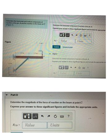
Transcribed Image Text:Determine the horizontal and vertical components of
reaction at the pin A and the reaction on the beam at C.
(Figure 1)
Determine the horizontal component of reaction at the pin A
Express your answer to three significant figures and include the appropriate
Figure
1.5 m
1.5 m
μA
A₁ =
Value
< 1 of 1
Submit
Request Answer
1.5 m-
4 KN
Part C
B
2¢
?
Units
Determine the vertical component of reaction at the pin A
Express your answer to three significant figures and include the appropriate un
НА
C□?
D
Ay
Vahre
Units
X
Part D
Determine the magnitude of the force of reaction on the beam at point C.
Express your answer to three significant figures and include the appropriate units.
μA
0
?
FCD= Value
Units
Expert Solution
This question has been solved!
Explore an expertly crafted, step-by-step solution for a thorough understanding of key concepts.
Step by stepSolved in 2 steps with 2 images

Knowledge Booster
Similar questions
- The pillar crane is subjected to the crate having a mass of 600 kg. The boom is held in position shown in picture. a) Determine the force in the tie rod FAB b) Determine the horizontal and vertical reactions at the pin support C. Enter your answers in kilonewtons to three significant figures and separated by a comma.arrow_forward2.107 - This question asks to be solved using the ‘Dot Product’arrow_forwardThe homogeneous bar ABC is supported by a pin at C and a cable that runs from A to B around the frictionless pulley at D. Find the stress (in psi) in the cable if its diameter is d = 0.57 in and the weight of the bar is 5305 lb. Round off the final answer to three decimal places.arrow_forward
- Please no hand writing solutionarrow_forwardphyarrow_forwardnovig size modestib Beri N 1-12 12- 60° 37. A block-and-tackle pulley hoist is suspended in a warehouse ay by ropes of lengths 2 m and 3 m. The hoist weighs 350 N. The ropes, fastened at different heights, make angles of 50° and th 38° with the horizontal. Find the tension in each rope and the magnitude of each tension. 50° brd 60° 2 m 38° 3 m 501001 hon sit 44. 45 4arrow_forward
- 6arrow_forwardLooking for a handwritten solution. Include diagram and explanation. No gptarrow_forwardStructural member AB is supported by cable BC and at A by a square rod which fits loosely through the square hole in the collar fixed to the member. Two forces are applied to AB as shown. 1.5 m 3 m Determine: 400 N a. Support reactions at A b. Cable tension C Draw all FBD's needed to solve, show all work, and put units on your answers. 200 N x' 1 marrow_forward
- Support reactions? Kindly don't copy ,Solve it quick and clearly.arrow_forwardA 3.00 m long, 8.0 kg pole is attached to a wall by a hinge on its left side. A cable attached to the right end of the pole holds it horizontal. The cable attaches at a 55.0° angle. A 10.0 kg box hangs from the pole at a point 1.25 m from the right end of the pole. (see diagram) hinge. 55° 1,25m a) Write out the sum of the forces and sum of the torques equations. b) What will be the Tension on the cable? 10k₂ c) What will be the magnitude and direction of the force on the hinge?arrow_forwardFigure 1.5 m 2 m 2m 0.5m B 2 1m 2.5 m 4 m 1 of 1arrow_forward
arrow_back_ios
SEE MORE QUESTIONS
arrow_forward_ios
Recommended textbooks for you
 International Edition---engineering Mechanics: St...Mechanical EngineeringISBN:9781305501607Author:Andrew Pytel And Jaan KiusalaasPublisher:CENGAGE L

International Edition---engineering Mechanics: St...
Mechanical Engineering
ISBN:9781305501607
Author:Andrew Pytel And Jaan Kiusalaas
Publisher:CENGAGE L