Introductory Circuit Analysis (13th Edition)
13th Edition
ISBN: 9780133923605
Author: Robert L. Boylestad
Publisher: PEARSON
expand_more
expand_more
format_list_bulleted
Concept explainers
Question
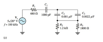
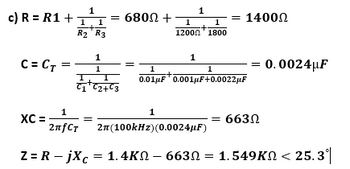
Please review my calculations for R, CT, XC, and Z for the circuit in the attached image, and let me know if I am working this correctly. Thanks!

Transcribed Image Text:5220⁰ V
f= 100 kHz
+₁
R₁
ww
6800
C₁
1000 pF
C₂
0.001 μF
R₂
· 1.2 ΚΩ
C₂
0.0022 μF
R₂
1800

Transcribed Image Text:c) R = R1 +
C = CT
1
1 1
+
R2 R3
XC =
=
1
2nfCT
Z = R – jXc
= 6800 +
1
1
CiC2463
1
1
1
·+·
12000 1800
1
1
= 14002
=
1
1
:+
0.01uF 0.001uF+0.0022pF
= 6630
0.0024uF
2n (100kHz) (0.0024UF)
1.4KQ – 6630 = 1.549KN < 25.3°|
Expert Solution
arrow_forward
Step 1

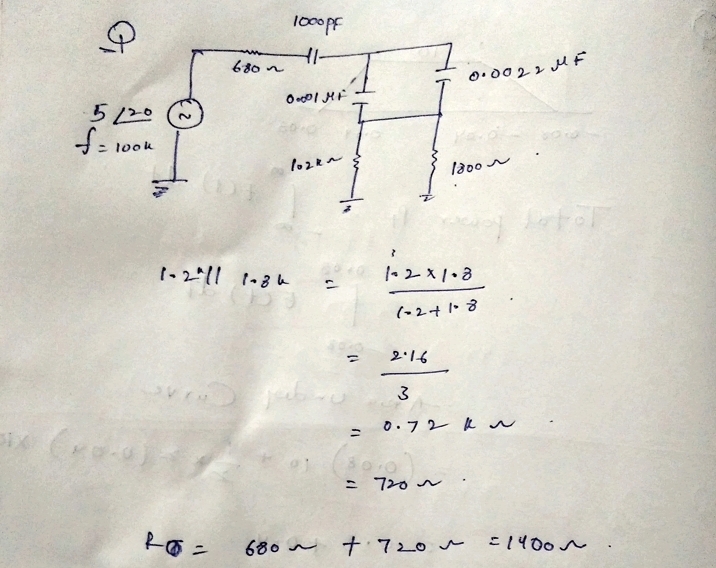
Step by stepSolved in 2 steps with 2 images

Knowledge Booster
Learn more about
Need a deep-dive on the concept behind this application? Look no further. Learn more about this topic, electrical-engineering and related others by exploring similar questions and additional content below.Similar questions
- A sensor needs a bias voltage of +3.000 volts. The DAC producing the voltage is 12 bits with a 3.3 volt reference. What is the DAC input code? 1241 3724 3103 3541arrow_forwardSolve thisarrow_forwardAn ideal ADC has a resolution of 6 bits and a conversion voltage range between -2 V and 4 V. What is the conversion resolution? Enter a value in millivolts (mV) to 2 decimal places.arrow_forward
- List the 8051 microcontroller's most important characteristics. Using a clean and well-labeled schematic, go through the basic block diagram of the microcontroller. Introductory course on embedded systemsarrow_forwardHow do CRTs create RGB colour beams?arrow_forwardQuestion 3 The 555 timer is connected in the following circuit. The resistance of the extra resistor is 102, the capacitance of the extra capacitor is 0.1F. The voltage input at Pin2 is Vcc. What is the output state at Pin3? 1) 2) Decide the voltage input value at Pin 6 when the condition is stable. 3) Decide the output state at Pin3 when a trigger input is applied at Pin2 (voltage input at Pin2 changes from Vcc to 0, and return back to Vcc immediately). 4) After the trigger input is applied at Pin2, how long would the output maintain at the unstable state. Vc R O Output Vo 555 Vc 0.01µF Trigger Inputarrow_forward
- What is the difference between these 2 signals: a(n) = (3)"-1u(n – 1) b(n) = (3)"-1u(n)arrow_forwardIs the small signal equivalent circuit for this diagram correct? How do we add cg and Cs?arrow_forwardConsider the circuit given, where R= 3 Q. lic 48 a3 X=0 10u(-t) mA 2 mF ? VC 250 mH Determine icO™). (You must provide an answer before moving on to the The value of ido*) is A. ellarrow_forward
arrow_back_ios
arrow_forward_ios
Recommended textbooks for you
 Introductory Circuit Analysis (13th Edition)Electrical EngineeringISBN:9780133923605Author:Robert L. BoylestadPublisher:PEARSON
 Delmar's Standard Textbook Of ElectricityElectrical EngineeringISBN:9781337900348Author:Stephen L. HermanPublisher:Cengage Learning
 Programmable Logic ControllersElectrical EngineeringISBN:9780073373843Author:Frank D. PetruzellaPublisher:McGraw-Hill Education
 Fundamentals of Electric CircuitsElectrical EngineeringISBN:9780078028229Author:Charles K Alexander, Matthew SadikuPublisher:McGraw-Hill Education
 Electric Circuits. (11th Edition)Electrical EngineeringISBN:9780134746968Author:James W. Nilsson, Susan RiedelPublisher:PEARSON
 Engineering ElectromagneticsElectrical EngineeringISBN:9780078028151Author:Hayt, William H. (william Hart), Jr, BUCK, John A.Publisher:Mcgraw-hill Education,

Introductory Circuit Analysis (13th Edition)
Electrical Engineering
ISBN:9780133923605
Author:Robert L. Boylestad
Publisher:PEARSON

Delmar's Standard Textbook Of Electricity
Electrical Engineering
ISBN:9781337900348
Author:Stephen L. Herman
Publisher:Cengage Learning

Programmable Logic Controllers
Electrical Engineering
ISBN:9780073373843
Author:Frank D. Petruzella
Publisher:McGraw-Hill Education

Fundamentals of Electric Circuits
Electrical Engineering
ISBN:9780078028229
Author:Charles K Alexander, Matthew Sadiku
Publisher:McGraw-Hill Education

Electric Circuits. (11th Edition)
Electrical Engineering
ISBN:9780134746968
Author:James W. Nilsson, Susan Riedel
Publisher:PEARSON

Engineering Electromagnetics
Electrical Engineering
ISBN:9780078028151
Author:Hayt, William H. (william Hart), Jr, BUCK, John A.
Publisher:Mcgraw-hill Education,