
Introductory Circuit Analysis (13th Edition)
13th Edition
ISBN: 9780133923605
Author: Robert L. Boylestad
Publisher: PEARSON
expand_more
expand_more
format_list_bulleted
Related questions
Concept explainers
Question
Please Use matrix form in solving this problem. Thank you
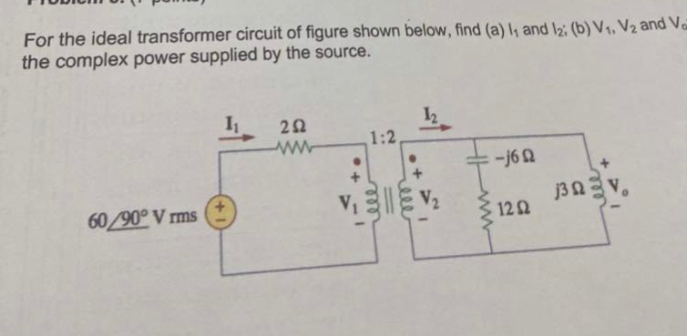

Transcribed Image Text:For the ideal transformer circuit of figure shown below, find (a) 1₁ and 12: (b) V₁, V2 and Va
the complex power supplied by the source.
60/90° Vrms
1₁
292
wwwww
1:2.
-j6
1202
j30
Expert Solution
This question has been solved!
Explore an expertly crafted, step-by-step solution for a thorough understanding of key concepts.

This is a popular solution

Trending nowThis is a popular solution!

Step by stepSolved in 3 steps with 3 images

Knowledge Booster


Learn more about
Need a deep-dive on the concept behind this application? Look no further. Learn more about this topic, electrical-engineering and related others by exploring similar questions and additional content below.Similar questions
- My professor JUST sent me this "question" as a HW assignment, can someone explain to me what he wants me to do? Implement the Simple adder with Sum and Carry, and generate the simplified equations from the k-Maparrow_forwardCreate a K-map for (A + B’)(A + B + C’)(B + C)arrow_forward5. a. Convert the following expressions into a sum-of-products (SOP) form: (A +B)(C+B) (A +BC)C b. Cany out the following computations in 2's complement: i. 27-21 ii. 35-43arrow_forward
- Shown on the right is a circuit consists of six identical resistors with resistance R, and a battery of emf E. (a) Find the power supplied by the battery. R (b) Find the current flowing through the middle resistor (a). Hint: As always, you can use the fundamental way to solve this problem. It is doable, although the algebra can be complicated. Alternatively, think about symmetry and remember that resistors only have currents when there is a nonzero voltage across it. R www- R 3,arrow_forwardPlease answer in typing format solution please only typing format solution please only Please answer all subparts is compulsory to answer in typing format solution pleasearrow_forward
arrow_back_ios
arrow_forward_ios
Recommended textbooks for you
- Introductory Circuit Analysis (13th Edition)Electrical EngineeringISBN:9780133923605Author:Robert L. BoylestadPublisher:PEARSON
 Delmar's Standard Textbook Of ElectricityElectrical EngineeringISBN:9781337900348Author:Stephen L. HermanPublisher:Cengage Learning
 Programmable Logic ControllersElectrical EngineeringISBN:9780073373843Author:Frank D. PetruzellaPublisher:McGraw-Hill Education
  Fundamentals of Electric CircuitsElectrical EngineeringISBN:9780078028229Author:Charles K Alexander, Matthew SadikuPublisher:McGraw-Hill Education
 Electric Circuits. (11th Edition)Electrical EngineeringISBN:9780134746968Author:James W. Nilsson, Susan RiedelPublisher:PEARSON
 Engineering ElectromagneticsElectrical EngineeringISBN:9780078028151Author:Hayt, William H. (william Hart), Jr, BUCK, John A.Publisher:Mcgraw-hill Education,
Introductory Circuit Analysis (13th Edition)
Electrical Engineering
ISBN:9780133923605
Author:Robert L. Boylestad
Publisher:PEARSON
Delmar's Standard Textbook Of Electricity
Electrical Engineering
ISBN:9781337900348
Author:Stephen L. Herman
Publisher:Cengage Learning
Programmable Logic Controllers
Electrical Engineering
ISBN:9780073373843
Author:Frank D. Petruzella
Publisher:McGraw-Hill Education
Fundamentals of Electric Circuits
Electrical Engineering
ISBN:9780078028229
Author:Charles K Alexander, Matthew Sadiku
Publisher:McGraw-Hill Education
Electric Circuits. (11th Edition)
Electrical Engineering
ISBN:9780134746968
Author:James W. Nilsson, Susan Riedel
Publisher:PEARSON
Engineering Electromagnetics
Electrical Engineering
ISBN:9780078028151
Author:Hayt, William H. (william Hart), Jr, BUCK, John A.
Publisher:Mcgraw-hill Education,