Introductory Circuit Analysis (13th Edition)
13th Edition
ISBN: 9780133923605
Author: Robert L. Boylestad
Publisher: PEARSON
expand_more
expand_more
format_list_bulleted
Question
NOTE: Polar form for Voltage & Current. Rectangular form for Impedance
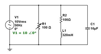
Find the total impedance of the circuit, total power (apparent) delivered by the current source, Draw the phasor diagram of the voltage and current at the source, the current passing through the R2 and L1 branch, Draw the phasor diagram of the voltage and current at the R2 and L1 branch. Also, is the circuit inductive, capacitive, or neither (resistive)?

Transcribed Image Text:-2
V1
10 Vrms
50Hz
0°
V1 = 10 20°
R1
100 Ω
R2
10022
L1
320mH
C1
16μF
Expert Solution
This question has been solved!
Explore an expertly crafted, step-by-step solution for a thorough understanding of key concepts.
Step by stepSolved in 5 steps with 5 images

Knowledge Booster
Learn more about
Need a deep-dive on the concept behind this application? Look no further. Learn more about this topic, electrical-engineering and related others by exploring similar questions and additional content below.Similar questions
- Use mesh current analysis to find the phasor currents. Vl = 12020° V .... ... ... ... .... ... .... ... ... .. ... R1 .. R2 200 R3 300 300 L1 L2 ... .... 140: L3 120 .. 110 ... ... . .. ...arrow_forward9. An electric circuit consists of two components as shown in the figure below. Z1 R₁ www XL 1 00000 = Z2 HE The generalisation of the resistance and reactance to an AC circuit is a complex number, known as impedance. For the electrical circuit pictured above, the impedance of the first component can be expressed by z₁ = R₁ + X₁i and the impedance of the second component can be expressed by z2 = R₂ - Xci, where R₁ = 3 Q2, XL = 32, R₂ = 42, and Xc = 422. Z Z1 Z2 R2 For electrical circuits connected in parallel, as shown above, the total impendance z of the circuit can be computed using the relationship Xc (a) Compute the total impedance z of the two components. (b) What are the modulus and principal argument of the total impedance?arrow_forwardKindly choose the appropriate and best answer.arrow_forward
- 6-10) Using what you have learned constructing the phasor diagram for the LRC series circuit, construct a diagram for the LRC parallel circuit. Derive an expression for the circuit impedance Z and the phase angle φ between the applied emf and the current supplied by the emf. HINT: in the series circuit, the current through all four components was the same. Ask yourself what the components in this arrangement have in common.arrow_forward3&page%3D1 American Uni. Girne American Uni.. O portal.gaueng.org My Profile - Zoom Dashboard My Courses This course Find the Norton equivalent of the circuit 60 30 40V ,50 202 A BI E E E E ere to searcharrow_forwardConsider the following circuit used to provide power for an induative RL load. The input voltage is V-100V and the load has a 50 impedance value. The thyristor is working at a frequency fs = 2 kHz. The discharge current is to be limited to 40A and the required dv/dt is 40V/us. If the value of Ce is equal to 0.14uF, then the snubber losses are equal to: R. V. Select one: O a 5.4W O b. 7.4W 1.4W Od. 3.4Warrow_forward
- An impedance z₁ = 8j5ohms is in parallel with an impedance z₂ = 3 + j7ohms. If 100V are imposed on the parallel combination. Find the branch current 11, 12 and the resultant current. Draw the corresponding phasor diagram showing each current and voltage drop across each parameter. Calculate also the equivalent resistance, reactance and impedance of the whole circuit.arrow_forwardTopic: Characteristics of Sinusoids Prove the answer.arrow_forwardFind the total impedance, voltage drop on the 100-ohm resistor, draw the phasor diagram of the voltage and current at R1, total power (apparent) delivered by the current source, draw the phasor diagram of the voltage and current at the source. Also, is the circuit inductive, capacitive, or neither (resistive)? please give the step-by-step solution NOTE: Polar form for Voltage & Current. Rectangular form for Impedancearrow_forward
arrow_back_ios
arrow_forward_ios
Recommended textbooks for you
 Introductory Circuit Analysis (13th Edition)Electrical EngineeringISBN:9780133923605Author:Robert L. BoylestadPublisher:PEARSON
 Delmar's Standard Textbook Of ElectricityElectrical EngineeringISBN:9781337900348Author:Stephen L. HermanPublisher:Cengage Learning
 Programmable Logic ControllersElectrical EngineeringISBN:9780073373843Author:Frank D. PetruzellaPublisher:McGraw-Hill Education
 Fundamentals of Electric CircuitsElectrical EngineeringISBN:9780078028229Author:Charles K Alexander, Matthew SadikuPublisher:McGraw-Hill Education
 Electric Circuits. (11th Edition)Electrical EngineeringISBN:9780134746968Author:James W. Nilsson, Susan RiedelPublisher:PEARSON
 Engineering ElectromagneticsElectrical EngineeringISBN:9780078028151Author:Hayt, William H. (william Hart), Jr, BUCK, John A.Publisher:Mcgraw-hill Education,

Introductory Circuit Analysis (13th Edition)
Electrical Engineering
ISBN:9780133923605
Author:Robert L. Boylestad
Publisher:PEARSON

Delmar's Standard Textbook Of Electricity
Electrical Engineering
ISBN:9781337900348
Author:Stephen L. Herman
Publisher:Cengage Learning

Programmable Logic Controllers
Electrical Engineering
ISBN:9780073373843
Author:Frank D. Petruzella
Publisher:McGraw-Hill Education

Fundamentals of Electric Circuits
Electrical Engineering
ISBN:9780078028229
Author:Charles K Alexander, Matthew Sadiku
Publisher:McGraw-Hill Education

Electric Circuits. (11th Edition)
Electrical Engineering
ISBN:9780134746968
Author:James W. Nilsson, Susan Riedel
Publisher:PEARSON

Engineering Electromagnetics
Electrical Engineering
ISBN:9780078028151
Author:Hayt, William H. (william Hart), Jr, BUCK, John A.
Publisher:Mcgraw-hill Education,