Introductory Circuit Analysis (13th Edition)
13th Edition
ISBN: 9780133923605
Author: Robert L. Boylestad
Publisher: PEARSON
expand_more
expand_more
format_list_bulleted
Concept explainers
Question
Needs Complete typed solution with 100 % accuracy.

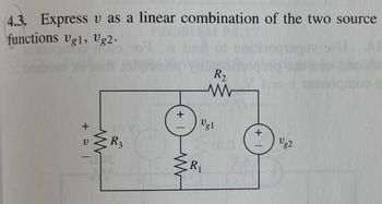
Transcribed Image Text:4.3. Express v as a linear combination of the two source
functions Vg1, Vg2.
+21
www
V
R3
(+1)
R₂
www
Vg1
{R₁
+
Vg2
Expert Solution
This question has been solved!
Explore an expertly crafted, step-by-step solution for a thorough understanding of key concepts.
This is a popular solution
Trending nowThis is a popular solution!
Step by stepSolved in 3 steps with 4 images

Knowledge Booster
Learn more about
Need a deep-dive on the concept behind this application? Look no further. Learn more about this topic, electrical-engineering and related others by exploring similar questions and additional content below.Similar questions
- Hello. I am working through some practice and I wanted to get some help going through this problem. I am working through with just the formulas through the integration rather than acutal numbers and values. Thank you for your time and effort.arrow_forwardsolve the following:arrow_forward(a) Use Ohm's Law to derive an expression relating Vout to Vin using the values of the two resistors. For this calculation, assume that you have no load attached (i.e. RL → xx). Make sure to explain in words each step you take. Hint: Vout is just the voltage drop across R2. You can draw in a battery with AV = Vin if that helps you set up the relationships. R1 Vin R2 Vout (O Vin- Your answer should be in the form, Vout The term in parentheses is called the gain of the divider, or the divider ratio. in· wwarrow_forward
- Determine the values of the node voltages of the circuit shown. 5 V 20 2 U2 82 12 2 U3 v1 U4 (1)1.25 A 40 2 O 15 V 6:05 PM 50°F Clear 2/18/2022 P Type here to search Home F9 End F10 PgUp PgDn F12 Del DII PrtScn F11 Esc F6 F1 @ %23 2$ % & Backs 2 4. 5 6 7 9.arrow_forwardCan you solve this problem ? thank you..arrow_forwardP7arrow_forward
- Consider the circuit shown below. R1 = 100 N R2 = 100 N C1 10 mF V = 12 V R3 3 100 N C, = 4.7 mF %3D %3D a. After the switch has been closed for a very long time, what are the voltages across the capacitors C1 and C2? Hint for (a) Voltage across C1 is V, and voltage across C2 is V. b. After the switch has been closed for a very long time, what is the energy stored in each capacitor? Hint for (b) Energy stored on C, is J, and energy stored on C, is J.arrow_forwardan | Schoc X O https://ti-submission-google.a x submission-google.app.schoology.com/assignment/student/59013660 M maaoun4@hawkm. Course: Student R.. Current Students.. 6 Home | Schoology M Inbox (2,780) - 20. Q Student Portal D DocHub - Circuits Lab Simulation - 10382745 * ew Insert Format Tools Add-ons Help Last edit was made 10 minutes ago by Zainab Chebib Comic San. A E = = = E E - E - E E 100% - Normal text 12 I 3 I.. 4 10. Keep Te vUTTery vurue Tre sume unu vuru uriTTIer puruneI Cirtur TIEXT TO TIE TrST puruner circuit using 3 light bulbs. 19. Compare the brightness of 2 light bulbs wired in parallel relative to the brightness of 3 light bulbs wired in parallel. Tap circuit element to edit. a. Based on the length of the light rays, when a third light bulb is added in parallel the brightness of each bulb MacBook Pro 吕口 F10 F7 F2 F4 & * %23 3 24 4. 5 6 E Y U D F G H J K Larrow_forwardGive an independent set of linear that can ve solved for the current shown. Use the Junction Rulearrow_forward
- Just like resistors, impedance values can be combined in series or in parallel. We combine them in the same way as combining resistors, i.e., for the series connection: Zeg Z1+22+ Z3+.... For the parallel connection: Zeq = (Z+Z+Z3+...) What is the equivalent impedance of the following circuit? (Hint: you can use scientific calculator or MatLab to perform calculations involving complex numbers.) L 50 £2 300 1000 MO 400 200 102.2+19.8j O 102.2-19.8j -102.2+19.8j O-102.2 19.8jarrow_forwardHow do I solve this using Kirchoff's Voltage Law?arrow_forwardDetermine the range of K for which a system with the following characteristics equation is stable. S³ + 5s² + 7s + K = 0arrow_forward
arrow_back_ios
SEE MORE QUESTIONS
arrow_forward_ios
Recommended textbooks for you
 Introductory Circuit Analysis (13th Edition)Electrical EngineeringISBN:9780133923605Author:Robert L. BoylestadPublisher:PEARSON
 Delmar's Standard Textbook Of ElectricityElectrical EngineeringISBN:9781337900348Author:Stephen L. HermanPublisher:Cengage Learning
 Programmable Logic ControllersElectrical EngineeringISBN:9780073373843Author:Frank D. PetruzellaPublisher:McGraw-Hill Education
 Fundamentals of Electric CircuitsElectrical EngineeringISBN:9780078028229Author:Charles K Alexander, Matthew SadikuPublisher:McGraw-Hill Education
 Electric Circuits. (11th Edition)Electrical EngineeringISBN:9780134746968Author:James W. Nilsson, Susan RiedelPublisher:PEARSON
 Engineering ElectromagneticsElectrical EngineeringISBN:9780078028151Author:Hayt, William H. (william Hart), Jr, BUCK, John A.Publisher:Mcgraw-hill Education,

Introductory Circuit Analysis (13th Edition)
Electrical Engineering
ISBN:9780133923605
Author:Robert L. Boylestad
Publisher:PEARSON

Delmar's Standard Textbook Of Electricity
Electrical Engineering
ISBN:9781337900348
Author:Stephen L. Herman
Publisher:Cengage Learning

Programmable Logic Controllers
Electrical Engineering
ISBN:9780073373843
Author:Frank D. Petruzella
Publisher:McGraw-Hill Education

Fundamentals of Electric Circuits
Electrical Engineering
ISBN:9780078028229
Author:Charles K Alexander, Matthew Sadiku
Publisher:McGraw-Hill Education

Electric Circuits. (11th Edition)
Electrical Engineering
ISBN:9780134746968
Author:James W. Nilsson, Susan Riedel
Publisher:PEARSON

Engineering Electromagnetics
Electrical Engineering
ISBN:9780078028151
Author:Hayt, William H. (william Hart), Jr, BUCK, John A.
Publisher:Mcgraw-hill Education,