
Structural Analysis
6th Edition
ISBN: 9781337630931
Author: KASSIMALI, Aslam.
Publisher: Cengage,
expand_more
expand_more
format_list_bulleted
Related questions
Concept explainers
Question

Transcribed Image Text:### Problem Statement
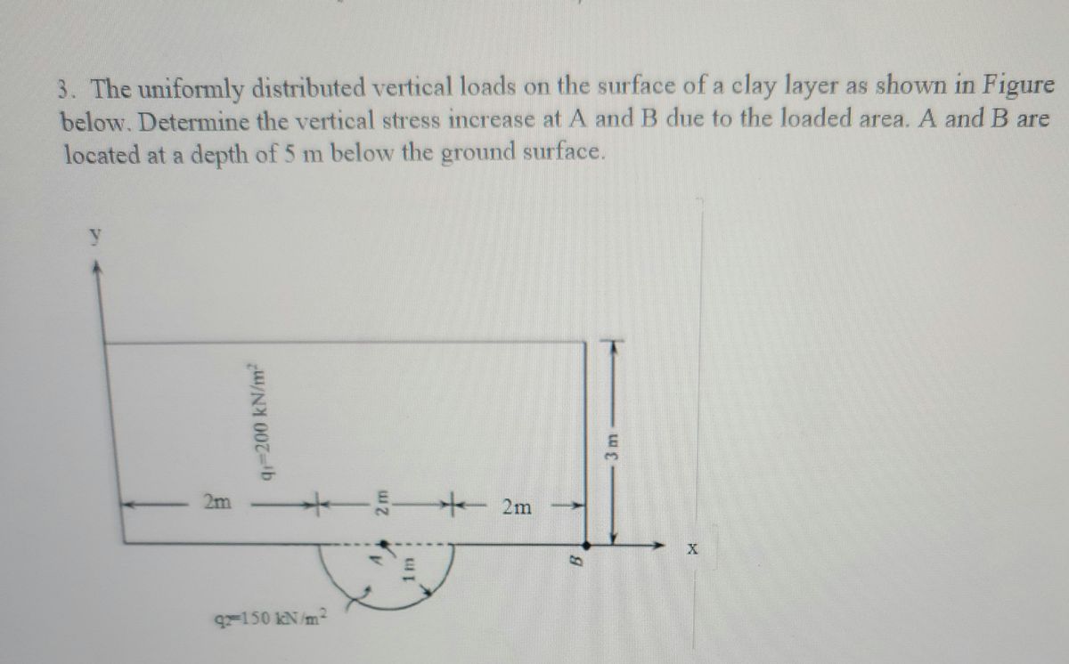
3. The uniformly distributed vertical loads on the surface of a clay layer are as shown in the figure below. Determine the vertical stress increase at points A and B due to the loaded area. Points A and B are located at a depth of 5 meters below the ground surface.
### Diagram Explanation
The diagram illustrates a rectangular plan view of a loaded area on the clay layer surface. The dimensions and load distributions are detailed as follows:
- The load is applied over a rectangular area.
- The load distribution is divided into two distinct sections:
- A central section with a uniform load of \( q = 200 \, \text{kN/m}^2 \), extending horizontally 4 meters (2 meters from the center in each direction).
- An additional section to the left, with a uniform load of \( q = 150 \, \text{kN/m}^2 \), extending 2 meters.
- The total width of the loaded area is 6 meters (2 meters on the left + 4 meters in the central section).
- The loaded area extends 3 meters in the y-direction.
Points A and B:
- Point A is located at the center, directly below the boundary between the 200 kN/m² and 150 kN/m² sections.
- Point B is located at the right boundary of the 200 kN/m² section, 3 meters from the vertical edge and within the horizontal plane containing points A and B.
Both points A and B are at a depth of 5 meters beneath the ground surface. The challenge involves determining the increase in vertical stress at these points due to the loads applied above.
Expert Solution
This question has been solved!
Explore an expertly crafted, step-by-step solution for a thorough understanding of key concepts.

This is a popular solution

Trending nowThis is a popular solution!

Step by stepSolved in 6 steps with 4 images

Knowledge Booster


Learn more about
Need a deep-dive on the concept behind this application? Look no further. Learn more about this topic, civil-engineering and related others by exploring similar questions and additional content below.Similar questions
- 4- Determine a suitable W profile to limit the maximum stress σd=200 MPaarrow_forward3- Due to application of line loads q1 and q2, the vertical stress increase at point A is 42 lb/ft?. Determine the magnitude of q2 q.=292 Ib/ft 92 45° 4.5 ft 3 ft 3 ft Aarrow_forwardthe profile of on 2 m from the load. 5-11 A uniform surface load of 220 kPa is applied over the area shown below. Estimate the stress increase in soil due to the surface load at a depth of 15 m below point A. 10 m 20 m IT 10 m Aarrow_forward
- The center of a rectangular area at the ground surface has Cartesian coordinates (0, 0), and one corner has coordinates (7, 18). All dimensions are in meters. The area carries a uniform pressure of 135 kPa. Estimate the stresses at a depth of 15 m below the ground surface at each of the following locations: (0, 0), (0, 18), (7, 0), (7, 18), and (12, 28).a. Obtain the values by the Boussinesq methodb. Compare the results with those of the 2:1 methodc. Comment on the resultsHint: In the Boussinesq method, the equations attached can be used.arrow_forward6- A flexible rectangular area is subjected to a uniformly distributed load of q=250 lb/ft?. Determine the increase in vertical stress at a depth of z=6 ft under points A, B, and C. 6 ft + 2.5 ft 3 ft 1.5 ft A C q=250 Ib/ft? 1.8 ftarrow_forwardThe cross-sectional area of bar ABCD is 500 mm^2 . Determine the stress in segment BCarrow_forward
- 1. The bar has a cross-sectional area of 400*106 m². If it is subjected to a uniform axial distributed loading along its length and to two concentrated loads, determine the average normal stress in the bar as a function of x, for 0.5 m < x≤ 1.25 m. -X 0.5 m w = 8 kN/m -6 kN 0.75 m 3 kNarrow_forwardProb. 3 The plan of a flexible rectangular loaded area is shown in Figure below. The uniformly distributed load on the flexible area, q, is 100 kN/m². Determine the increase in the vertical stress, Aoz, at a depth of z = 2 m below a. Point A b. Point B c. Point C 4 m 1.6 m 2 m 0.8 m q = 100 kN/m² A 1.2 m-arrow_forwardA concentrated load of 2200 kN is applied to the ground surface. Detemine the vertical stress increment due to this load at a point 6 m. below the ground surface and 4.8 m horizontally from the line of the concentrated load. Use Westergaard equation. #32 P=2200 kN z=6m A r-4.8marrow_forward
arrow_back_ios
arrow_forward_ios
Recommended textbooks for you
 Structural Analysis (10th Edition)Civil EngineeringISBN:9780134610672Author:Russell C. HibbelerPublisher:PEARSON
 Principles of Foundation Engineering (MindTap Cou...Civil EngineeringISBN:9781337705028Author:Braja M. Das, Nagaratnam SivakuganPublisher:Cengage Learning
 Fundamentals of Structural AnalysisCivil EngineeringISBN:9780073398006Author:Kenneth M. Leet Emeritus, Chia-Ming Uang, Joel LanningPublisher:McGraw-Hill Education
 Traffic and Highway EngineeringCivil EngineeringISBN:9781305156241Author:Garber, Nicholas J.Publisher:Cengage Learning
Structural Analysis (10th Edition)
Civil Engineering
ISBN:9780134610672
Author:Russell C. Hibbeler
Publisher:PEARSON
Principles of Foundation Engineering (MindTap Cou...
Civil Engineering
ISBN:9781337705028
Author:Braja M. Das, Nagaratnam Sivakugan
Publisher:Cengage Learning
Fundamentals of Structural Analysis
Civil Engineering
ISBN:9780073398006
Author:Kenneth M. Leet Emeritus, Chia-Ming Uang, Joel Lanning
Publisher:McGraw-Hill Education
Traffic and Highway Engineering
Civil Engineering
ISBN:9781305156241
Author:Garber, Nicholas J.
Publisher:Cengage Learning