Structural Analysis
6th Edition
ISBN: 9781337630931
Author: KASSIMALI, Aslam.
Publisher: Cengage,
expand_more
expand_more
format_list_bulleted
Concept explainers
Question
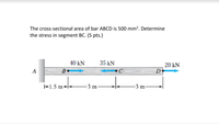
The cross-sectional area of bar ABCD is 500 mm^2 . Determine the stress in segment BC

Transcribed Image Text:The cross-sectional area of bar ABCD is 500 mm². Determine
the stress in segment BC. (5 pts.)
40 kN
35 kN
20 kN
B.
D
+1.5 m++
3 m
3 m
Expert Solution
This question has been solved!
Explore an expertly crafted, step-by-step solution for a thorough understanding of key concepts.
Step by stepSolved in 2 steps

Knowledge Booster
Learn more about
Need a deep-dive on the concept behind this application? Look no further. Learn more about this topic, civil-engineering and related others by exploring similar questions and additional content below.Similar questions
- The state of stress at a point is shown on the element. Enter your answers numerically separated by commas. ΥΠ ΑΣφ vec max min = ksi Submit Request Answer Figure Part B Determine the absolute maximum shear stress. ΑΣφ ve 2.5 ksi ksi Fabs mar= 4 ksi Submit Request Answer 5 ksi Provide Feedback 圓arrow_forwardIn the following structure, determine the stress in each bar. Indicate whether the stress is tensile or compressive. The area of each bar is indicated in this figure. Answ. AB = 8.33 ksi (C), BC = 8.33 ksi (C), DE = 25 ksi (T), AD = 16.6667 ksi (T), BE = 8.33 ksi (T), AE = 27.77 ksi (C)¸ CE = 10.41667 ksi (T).arrow_forwardConsider a point in a structural member that is subjected to plane stress. Normal and shear stresses acting on horizontal and vertical planes at the point are shown. If o = 25 MPa in the direction shown, determine the principal stresses at the point. 28 MPa 16 MPa O 39.2 MPa and -30.2 MPa O 31.6 MPa and -35.8 MPa 54.1 MPa and -41.3 MPa 35.8 MPa and -27.4 MPa O 27.7 MPa and -39.0 MPa Save for Later eTextbook and Media Attempts: 1 of 3 used Submit Answerarrow_forward
- Please use Mohr's Circle.arrow_forwardThe state of stress at a point in a member is shown on the element. Determine the principal normal stresses and their orientation and the maximum in-plane shear stress and their orientation. Draw Mohr’'s circle and Show results on properly oriented elements. -60 30 -50 40 -40 T-30 30 30 -20 40 30 -10 -60 -50 -40 -30 -20 -10 30 40 50 10 20 бо 10 20 30 40 50 60arrow_forwardCalculate the design moment strength Mu for the following section. Take f'c = 40 MPa. Sketch the strain and stress distribution diagrams for each section and try to work out your solutions using equilibrium conditions. Yield stress for N bars is 500 MPa. 75 700 60 1500 T 4N28 450arrow_forward
arrow_back_ios
arrow_forward_ios
Recommended textbooks for you

 Structural Analysis (10th Edition)Civil EngineeringISBN:9780134610672Author:Russell C. HibbelerPublisher:PEARSON
 Principles of Foundation Engineering (MindTap Cou...Civil EngineeringISBN:9781337705028Author:Braja M. Das, Nagaratnam SivakuganPublisher:Cengage Learning
 Fundamentals of Structural AnalysisCivil EngineeringISBN:9780073398006Author:Kenneth M. Leet Emeritus, Chia-Ming Uang, Joel LanningPublisher:McGraw-Hill Education
 Traffic and Highway EngineeringCivil EngineeringISBN:9781305156241Author:Garber, Nicholas J.Publisher:Cengage Learning


Structural Analysis (10th Edition)
Civil Engineering
ISBN:9780134610672
Author:Russell C. Hibbeler
Publisher:PEARSON

Principles of Foundation Engineering (MindTap Cou...
Civil Engineering
ISBN:9781337705028
Author:Braja M. Das, Nagaratnam Sivakugan
Publisher:Cengage Learning

Fundamentals of Structural Analysis
Civil Engineering
ISBN:9780073398006
Author:Kenneth M. Leet Emeritus, Chia-Ming Uang, Joel Lanning
Publisher:McGraw-Hill Education


Traffic and Highway Engineering
Civil Engineering
ISBN:9781305156241
Author:Garber, Nicholas J.
Publisher:Cengage Learning