
Elements Of Electromagnetics
7th Edition
ISBN: 9780190698614
Author: Sadiku, Matthew N. O.
Publisher: Oxford University Press
expand_more
expand_more
format_list_bulleted
Related questions
Question

Transcribed Image Text:=
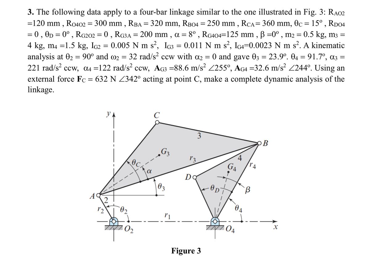
3. The following data apply to a four-bar linkage similar to the one illustrated in Fig. 3: RA02
=120 mm, R0402 = 300 mm, RBA = 320 mm, RB04 = 250 mm, RCA = 360 mm, 0c = 15°, RD04
= 0, 0D = 0°, RG202 = 0, RG3A = 200 mm, α = 8°, RG404=125 mm, ẞ =0°, m2 = 0.5 kg, m3 =
4 kg, m4 =1.5 kg, IG2 = 0.005 N m s², IG3 0.011 N m s², IG4=0.0023 N m s². A kinematic
analysis at 02 = 90° and 2 = 32 rad/s² ccw with α2 = 0 and gave 03 = 23.9°. 04 = 91.7º, α3 =
221 rad/s² ccw, α4 =122 rad/s² ccw, AG3 =88.6 m/s² 255°, AG4 =32.6 m/s² 244°. Using an
external force Fc = 632 N Z342° acting at point C, make a complete dynamic analysis of the
linkage.
C
УА
3
B
G₁₂
4
13
GA
TA
Ꭰ
Do
B
02
3
A
2
12
04
02
r1
X
04
Figure 3
Expert Solution
This question has been solved!
Explore an expertly crafted, step-by-step solution for a thorough understanding of key concepts.

Step by stepSolved in 2 steps with 1 images

Knowledge Booster

Similar questions
- Given a fourbar linkage (not drawn in scale) with the link lengths L2 = a = 6 cm, L3 = b = 25 cm, L4 = c = 30 cm, L1 = d = 12 cm and θ2 = 450. For RP = 4 cm, θ3 = 87.80, θ4 = 103.10, δ3 = 450, ω2 = 10 rad/s, ω3 = -7.7 rad/s, ω4 = -5.2 rad/s and α2 = 10 rad/sec2, the angular acceleration of link 3, α3 is equal toarrow_forwardFind the following degree of freedom using the formula below M = 3 (n-1) - j1 - j2 M = Mobility or Total no. of DOFn = Total no. of links in a mechanismJ1 = No. of joints having 1 DOFJ2 = No. of joints having 2 DOFarrow_forwardGiven the mechanism in Question #6, and L1 = 0.7 in, L2= 4 in, L3 = 7.5 in, and 02 = 18.6 deg: What is the value of angle y (gamma) in deg?arrow_forward
- Problem 4 For the 6 bar Watt's mechanism shown below, the link lengths are as follows: O2A = 1, AB = 1.2, 0204 = 2, 04B = 2, 0406 = 1.9, 06D = 2.4, CD = 1. Also O4C = 04B = BC. The input angle is 02. For 02 = 45 degrees, find the positions of the moving pivots A, B, C, and D in the global coordinate system YO2X. 0406 makes an angle of -30 degrees with the horizontal axis. [25 points] C Y R6 B D R3 A R5 R4 R7 X R2 RI Rs 04 02 06 Figure 4: Watt's mechanismarrow_forwardThe Figure below shows a sixbar linkage with 02B = 1, BD = 2, DC = 4, DO, = 3, and h = 1.3 in. Use analytical method to find the m3, a3, Ac , Ap, a6 if wz is a constant 1 rad/sec CCW. Vp-0.6 in/sec, Vslip-0.75 in/sec, ApBslip=1.03 in/sec? 6. 06 B 4 3 45° 02arrow_forwardIf the link lengths of a four-bar linkage are L1 = 1 mm, L2 = 3 mm, L3 = 4 mm,and L4 = 5 mm and link 1 is fixed, what type of four-bar linkage is it? Also, is the linkage a Grashof type 1 or 2 linkage? Answer the same questions if L1 = 2 mm.arrow_forward
- Example Problem 4-1, (page 141). [Ref.1]: The shaft shown in Figure 4-7 is supported by two bearings and carries two V-belt sheaves. The tensions in the belts exert horizontal forces on the shaft, tending to bend it in the X-Z plane. Sheave B exerts a clockwise torque on the shaft when viewed toward the origin of the coordinate system along the X-axis. Sheave C exerts an equal but opposite torque on the shaft. For the loading condition shown, determine the principal stresses and the maximum shear stress on element K on the front surface of the shaft (on the positive Z-side) just to the right of sheave B, Follow the general procedure for analyzing combined stresses given in this section. Page 2 of 8 100 mm 100 mm 50 mm Stress T B element. T. 50 mm 100 mm в 100 mm C D Shaft dia. = 32 mm FB=2440 N Fc=1220 N RD T= Torque = 120 N.m (b) Forces acting on shaft at B and C caused by belt drives (a) Pictorial view of shaftarrow_forwardQUESTION 1 Consider a 2 DOF system shown below. X1 k₁ m1 F₁ k₂ X2 k3 m₂ F2 The modeshape can be written as (1))] What is x for the second modeshape? Use scientific notation with 3 significant digits and omit units. (eg. -0.123) Let m1 = 2, m2 = 2, k1 = 9, k2 = 8, and k3 = 8.arrow_forwardParts A and B please. Thanksarrow_forward
arrow_back_ios
SEE MORE QUESTIONS
arrow_forward_ios
Recommended textbooks for you
- Elements Of ElectromagneticsMechanical EngineeringISBN:9780190698614Author:Sadiku, Matthew N. O.Publisher:Oxford University Press
 Mechanics of Materials (10th Edition)Mechanical EngineeringISBN:9780134319650Author:Russell C. HibbelerPublisher:PEARSON
 Thermodynamics: An Engineering ApproachMechanical EngineeringISBN:9781259822674Author:Yunus A. Cengel Dr., Michael A. BolesPublisher:McGraw-Hill Education
  Control Systems EngineeringMechanical EngineeringISBN:9781118170519Author:Norman S. NisePublisher:WILEY
 Mechanics of Materials (MindTap Course List)Mechanical EngineeringISBN:9781337093347Author:Barry J. Goodno, James M. GerePublisher:Cengage Learning
 Engineering Mechanics: StaticsMechanical EngineeringISBN:9781118807330Author:James L. Meriam, L. G. Kraige, J. N. BoltonPublisher:WILEY
Elements Of Electromagnetics
Mechanical Engineering
ISBN:9780190698614
Author:Sadiku, Matthew N. O.
Publisher:Oxford University Press
Mechanics of Materials (10th Edition)
Mechanical Engineering
ISBN:9780134319650
Author:Russell C. Hibbeler
Publisher:PEARSON
Thermodynamics: An Engineering Approach
Mechanical Engineering
ISBN:9781259822674
Author:Yunus A. Cengel Dr., Michael A. Boles
Publisher:McGraw-Hill Education
Control Systems Engineering
Mechanical Engineering
ISBN:9781118170519
Author:Norman S. Nise
Publisher:WILEY
Mechanics of Materials (MindTap Course List)
Mechanical Engineering
ISBN:9781337093347
Author:Barry J. Goodno, James M. Gere
Publisher:Cengage Learning
Engineering Mechanics: Statics
Mechanical Engineering
ISBN:9781118807330
Author:James L. Meriam, L. G. Kraige, J. N. Bolton
Publisher:WILEY