
Introductory Circuit Analysis (13th Edition)
13th Edition
ISBN: 9780133923605
Author: Robert L. Boylestad
Publisher: PEARSON
expand_more
expand_more
format_list_bulleted
Related questions
Concept explainers
Question
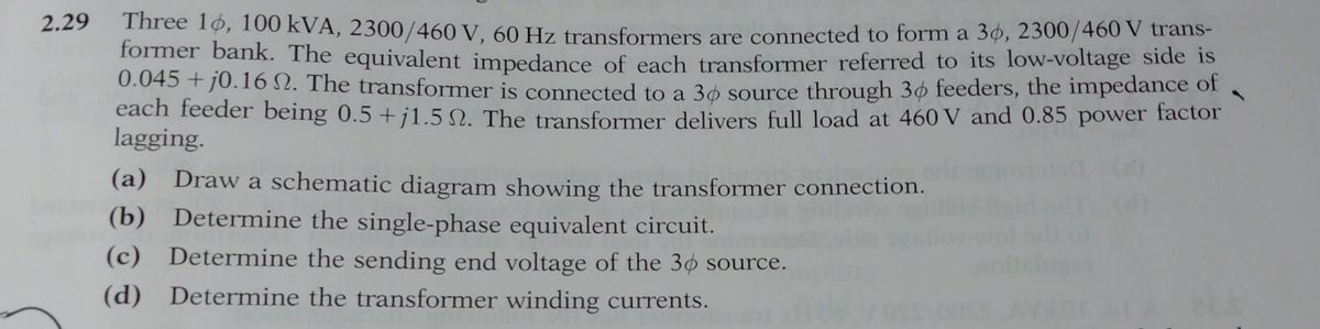

Transcribed Image Text:2.29
Three 10, 100 kVA, 2300/460 V, 60 Hz transformers are connected to form a 36, 2300/460 V trans-
former bank. The equivalent impedance of each transformer referred to its low-voltage side is
0.045 +10.16 2. The transformer is connected to a 36 source through 30 feeders, the impedance of
each feeder being 0.5 +j1.52. The transformer delivers full load at 460 V and 0.85 power factor
lagging.
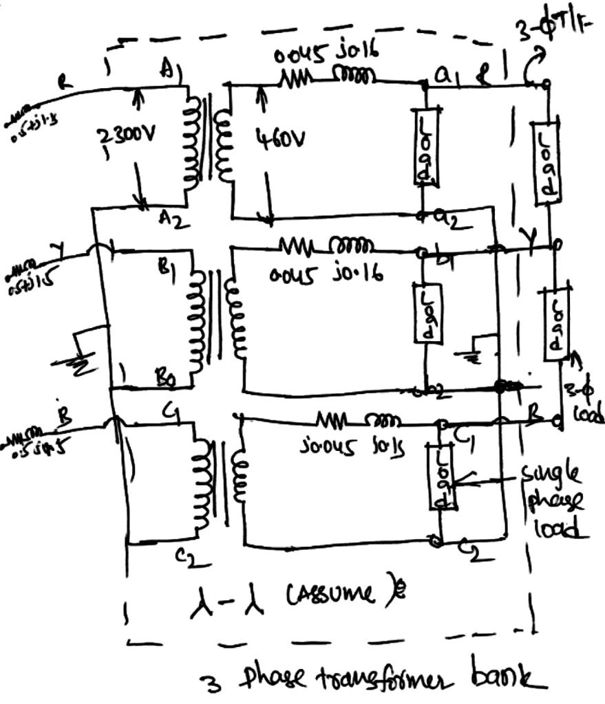
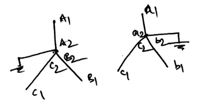
(a) Draw a schematic diagram showing the transformer connection.
(b) Determine the single-phase equivalent circuit.
(c) Determine the sending end voltage of the 30 source.
(d) Determine the transformer winding currents.
Expert Solution
arrow_forward
Step 1: Solution a
(a) Three-phase transformer schematic diagram:
format('truetype')%3Bfont-weight%3Anormal%3Bfont-style%3Anormal%3B%7D%3C%2Fstyle%3E%3C%2Fdefs%3E%3Ctext%20font-family%3D%22Arial%22%20font-size%3D%2216%22%20text-anchor%3D%22middle%22%20x%3D%2218.5%22%20y%3D%2216%22%3ETotal%3C%2Ftext%3E%3Ctext%20font-family%3D%22Arial%22%20font-size%3D%2216%22%20text-anchor%3D%22middle%22%20x%3D%2244.5%22%20y%3D%2216%22%3E3%3C%2Ftext%3E%3Ctext%20font-family%3D%22math180fb83078ae4686c8d6275d08d%22%20font-size%3D%2216%22%20text-anchor%3D%22middle%22%20x%3D%2256.5%22%20y%3D%2216%22%3E%26%23x2212%3B%3C%2Ftext%3E%3Ctext%20font-family%3D%22Arial%22%20font-size%3D%2216%22%20text-anchor%3D%22middle%22%20x%3D%2268.5%22%20y%3D%2216%22%3E%26%23x3D5%3B%3C%2Ftext%3E%3Ctext%20font-family%3D%22Arial%22%20font-size%3D%2216%22%20text-anchor%3D%22middle%22%20x%3D%22118.5%22%20y%3D%2216%22%3Etransformer%3C%2Ftext%3E%3Ctext%20font-family%3D%22Arial%22%20font-size%3D%2216%22%20text-anchor%3D%22middle%22%20x%3D%22179.5%22%20y%3D%2216%22%3EKVA%3C%2Ftext%3E%3Ctext%20font-family%3D%22math180fb83078ae4686c8d6275d08d%22%20font-size%3D%2216%22%20text-anchor%3D%22middle%22%20x%3D%22203.5%22%20y%3D%2216%22%3E%3D%3C%2Ftext%3E%3Ctext%20font-family%3D%22Arial%22%20font-size%3D%2216%22%20text-anchor%3D%22middle%22%20x%3D%22216.5%22%20y%3D%2216%22%3E3%3C%2Ftext%3E%3Ctext%20font-family%3D%22math180fb83078ae4686c8d6275d08d%22%20font-size%3D%2216%22%20text-anchor%3D%22middle%22%20x%3D%22228.5%22%20y%3D%2216%22%3E%26%23xD7%3B%3C%2Ftext%3E%3Ctext%20font-family%3D%22Arial%22%20font-size%3D%2216%22%20text-anchor%3D%22middle%22%20x%3D%22249.5%22%20y%3D%2216%22%3E100%3C%2Ftext%3E%3Ctext%20font-family%3D%22math180fb83078ae4686c8d6275d08d%22%20font-size%3D%2216%22%20text-anchor%3D%22middle%22%20x%3D%22271.5%22%20y%3D%2216%22%3E%3D%3C%2Ftext%3E%3Ctext%20font-family%3D%22Arial%22%20font-size%3D%2216%22%20text-anchor%3D%22middle%22%20x%3D%22293.5%22%20y%3D%2216%22%3E300%3C%2Ftext%3E%3Ctext%20font-family%3D%22Arial%22%20font-size%3D%2216%22%20text-anchor%3D%22middle%22%20x%3D%22323.5%22%20y%3D%2216%22%3EKVA%3C%2Ftext%3E%3C%2Fsvg%3E)

Step by stepSolved in 4 steps with 7 images

Knowledge Booster


Learn more about
Need a deep-dive on the concept behind this application? Look no further. Learn more about this topic, electrical-engineering and related others by exploring similar questions and additional content below.Similar questions
- Ql-phase step down transformer 1250 KVA, 10002200 V, 50 Hz The resistance /phase and leakage reactanceiphase of the primary winding are 0.78 2 and 4.82 and the corresponding values for the secondary winding are 0.012 and 0.002 respectively if the primary winding is connected in delta and secondary in star calculate: )The voltage to be applied at normal frequency to the primary to circulate full-load through it when the secondary is short-circuited li) The full load copper lossarrow_forwardWhen the transformer is loaded in a balanced fashion up to its nominal rating (10 MVA), calculate the high side line-to-line phasor voltages (ab, bc, ca). and low side phasor voltages both line-to-line and line-to-neutral (ab, bc, ca, a, b,c). as a reference for calculations the low side A line to neutral voltage is 7620V at an angle of 0 degrees when the transformer is at rated power. The transformer has the following characteristics: V: 138kV delta high side/ 13.2 kV wye low side 9% impedance X/R ratio of 20arrow_forward
Recommended textbooks for you
- Introductory Circuit Analysis (13th Edition)Electrical EngineeringISBN:9780133923605Author:Robert L. BoylestadPublisher:PEARSON
 Delmar's Standard Textbook Of ElectricityElectrical EngineeringISBN:9781337900348Author:Stephen L. HermanPublisher:Cengage Learning
 Programmable Logic ControllersElectrical EngineeringISBN:9780073373843Author:Frank D. PetruzellaPublisher:McGraw-Hill Education
  Fundamentals of Electric CircuitsElectrical EngineeringISBN:9780078028229Author:Charles K Alexander, Matthew SadikuPublisher:McGraw-Hill Education
 Electric Circuits. (11th Edition)Electrical EngineeringISBN:9780134746968Author:James W. Nilsson, Susan RiedelPublisher:PEARSON
 Engineering ElectromagneticsElectrical EngineeringISBN:9780078028151Author:Hayt, William H. (william Hart), Jr, BUCK, John A.Publisher:Mcgraw-hill Education,
Introductory Circuit Analysis (13th Edition)
Electrical Engineering
ISBN:9780133923605
Author:Robert L. Boylestad
Publisher:PEARSON
Delmar's Standard Textbook Of Electricity
Electrical Engineering
ISBN:9781337900348
Author:Stephen L. Herman
Publisher:Cengage Learning
Programmable Logic Controllers
Electrical Engineering
ISBN:9780073373843
Author:Frank D. Petruzella
Publisher:McGraw-Hill Education
Fundamentals of Electric Circuits
Electrical Engineering
ISBN:9780078028229
Author:Charles K Alexander, Matthew Sadiku
Publisher:McGraw-Hill Education
Electric Circuits. (11th Edition)
Electrical Engineering
ISBN:9780134746968
Author:James W. Nilsson, Susan Riedel
Publisher:PEARSON
Engineering Electromagnetics
Electrical Engineering
ISBN:9780078028151
Author:Hayt, William H. (william Hart), Jr, BUCK, John A.
Publisher:Mcgraw-hill Education,