
Delmar's Standard Textbook Of Electricity
7th Edition
ISBN: 9781337900348
Author: Stephen L. Herman
Publisher: Cengage Learning
expand_more
expand_more
format_list_bulleted
Related questions
Question
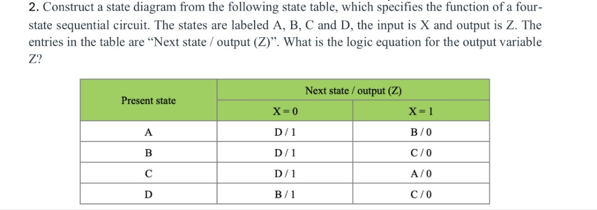

Transcribed Image Text:2. Construct a state diagram from the following state table, which specifies the function of a four-
state sequential circuit. The states are labeled A, B, C and D, the input is X and output is Z. The
entries in the table are "Next state / output (Z)". What is the logic equation for the output variable
Z?
Next state/output (Z)
Present state
X=0
X=1
A
D/1
B/0
B
D/1
C/O
C
D/1
A/0
D
B/1
C/0
Expert Solution
This question has been solved!
Explore an expertly crafted, step-by-step solution for a thorough understanding of key concepts.

Step by stepSolved in 2 steps with 10 images

Knowledge Booster

Similar questions
- From the BCD code whose block diagram is given in the figure below, you can find the 7-segment LED display (with common anode) code. Solving combinational logic circuit will be designed. This type of commercially produced decoder is integrated State the features you consider important by researching the circuits. BCD input at the output of the decoder For the 0-9 values of the information information, the following display figures will be seen and the values other than these it will be considered arbitrary. Since the 7-segment LED display has a common anode, Logic "0" will be applied in response to the burned parts. The accuracy of the logic circuit you will design Create the table and find the output expressions by shrinking the table with the Karnaugh diagram method.arrow_forwardWhat logic function is performed by this circuit? VDD a. O d. e. A b. None OC AB AB A+B A+B O f. B AB M₁ M₂ M3 M4 F M5arrow_forwardPlease can you help me And solve this problem I hope it includes a solution the k-map and logic circuit diagramarrow_forward
- Needs Complete solution with 100 % accuracy.arrow_forwardSequential circuit shown below has two flip-flops A and B and one input x. It consists of a combinatorial logic connected to the flip-flops, as shown in Figure below. Analyze the circuit: a. Derive the next state and output equations. b. The state table of the circuit. c. Draw the state diagram. A A' K 2to-1 , MUX Y B B' CLK loarrow_forwardHello I am having trouble with a practice problem for my digital circuits class. I would appreciate if you can help me out. Thanks.arrow_forward
- Draw a state diagram for: Mealy state machine to detect the 1010 sequence. The output becomes one when you receive the sequence of 1100 and the output is zero otherwise. Overlap is allowed between the detected sequences.arrow_forwardLogic circuit help please pleasearrow_forwardDIGITAL SYSTEMS - (logic gates) Please can you solve this question by simplifying the circuit in the simplest possible form. simplify 18 gates 10 to 15 output (E)arrow_forward
- I was able to fill out the truth table for part A. I ONLY need help for PART B. B) Implement the logic function (z) using the multiplexer 74HC151 shows in the picture.arrow_forward(b) Using a synchronous binary counter as shown in Figure Q2(b), design and draw a counter to generate the following repeating sequences 2 to 14 repeatedly for a free running clock. If the circuit happens to enter any of the states 15 or 0 or 1, what are the next states of your circuit? A A Syn. Binary Counter Q3 Q2 Q₁ Qo →Asyn. clear Syn. load CLK D3 D₂ D₁ Do ↑↑↑↑arrow_forwardConsider the circuit below. The switches are controlled by logic variables such that, if A is high, switch A is closed, and if A is low, switch A is open. Conversely, if B is high, the switch labeled is open, and if B is low, the switch labeled is closed. The output variable is high if the output voltage is 5V, and the output variable is low if the output voltage is zero. a. Write a logic expression for the output variable. b. Construct the truth table for the circuit. A Logic 1 5V(+ B C Logic 0 Rarrow_forward
arrow_back_ios
SEE MORE QUESTIONS
arrow_forward_ios
Recommended textbooks for you
- Delmar's Standard Textbook Of ElectricityElectrical EngineeringISBN:9781337900348Author:Stephen L. HermanPublisher:Cengage Learning
Delmar's Standard Textbook Of Electricity
Electrical Engineering
ISBN:9781337900348
Author:Stephen L. Herman
Publisher:Cengage Learning