Introductory Circuit Analysis (13th Edition)
13th Edition
ISBN: 9780133923605
Author: Robert L. Boylestad
Publisher: PEARSON
expand_more
expand_more
format_list_bulleted
Question
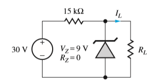
Load resistor RL as shown is 12 kΩ. What are the nominal and worst-case values of Zener diode current and power dissipation if the power supply voltage, Zener breakdown voltage and resistors all have 5 percent tolerances?

Transcribed Image Text:15 k2
RL
Vz=9 V
Rz=0
30 V
Expert Solution
This question has been solved!
Explore an expertly crafted, step-by-step solution for a thorough understanding of key concepts.
Step by stepSolved in 5 steps with 1 images

Knowledge Booster
Learn more about
Need a deep-dive on the concept behind this application? Look no further. Learn more about this topic, electrical-engineering and related others by exploring similar questions and additional content below.Similar questions
- diode? Under what circumstances does the output voltage remain constant in a limiter circuit with Zener When does the Z-current Iz begin to flow? Under what circumstances is the limiting effect maintained even under load?arrow_forwardHow can you use a zener diode? Please choose one: a. Voltage reference b. both of the above c. constant current source D. none of the abovearrow_forward5. Draw the Input/Output Vin/ Vout characteristic curve of the circuit given below. However, assume a Constant Voltage Diode Model and VB = 2 V. D₁ R₁ W VB MI D₂ R₂ Voutarrow_forward
- Q-2: The input signal for half-wave rectifier is a.c. signal. The output of 800 load resistor is 50V d.c. voltage. The diode has a resistance of 25 Q. 5 a) Draw the graphs of input signal, diode signal and output signals. 20 b) Calculate the maximum voltage value for the input signal. AC Supply Diode wwwarrow_forwardTopic: Half Wave Rectificationarrow_forwardOne component that does not need to be installed in the correct orientation is a: a. Resistorb. Diodec. Voltage regulatord.arrow_forward
- Please help me to understand this question. It's hard and challenging.arrow_forwardIn this Zener diode regulator, the source voltage varies from 6 V to 11 V. Assume that the load current varies between 2 mA and 48 mA, and that the diode is an ideal 4 V Zener diode. What is the largest allowable resistance that will ensure the load voltage remains constant with variations in load current and source voltage? Please enter your answer to 3 significant figures. Please answer in typing format solution please only typing format solution pleasearrow_forwardQ3: The figure below includes a bridge full-wave rectifier circuit with a diode type is1N4007. The input voltage is Vin V2 120 sin 2n60t 5:1 D3 D1 120 V RL Vp(out) D2 DA 10 kN a) Draw the output voltage waveform for the circuit in the figure and include thevoltage values. b) What is the peak inverse voltage (PIV) across each diode? c) Determine the rms voltage, current and power delivered to RL d) Determine the average voltage, current, and power delivered to RL e) What is the ratio of Po(de) to Po(ac)? lllarrow_forward
- A - Explain the symbols, operating principles and usage areas of the diodes given below. (Zener diode: photo diode: led diode: opto coupler) B- Draw the voltage trigger circuit and explain its operation. Explain how there is a difference between the voltage quadrant and the triplerarrow_forwardAnswer a,b,c,darrow_forward
arrow_back_ios
arrow_forward_ios
Recommended textbooks for you
 Introductory Circuit Analysis (13th Edition)Electrical EngineeringISBN:9780133923605Author:Robert L. BoylestadPublisher:PEARSON
 Delmar's Standard Textbook Of ElectricityElectrical EngineeringISBN:9781337900348Author:Stephen L. HermanPublisher:Cengage Learning
 Programmable Logic ControllersElectrical EngineeringISBN:9780073373843Author:Frank D. PetruzellaPublisher:McGraw-Hill Education
 Fundamentals of Electric CircuitsElectrical EngineeringISBN:9780078028229Author:Charles K Alexander, Matthew SadikuPublisher:McGraw-Hill Education
 Electric Circuits. (11th Edition)Electrical EngineeringISBN:9780134746968Author:James W. Nilsson, Susan RiedelPublisher:PEARSON
 Engineering ElectromagneticsElectrical EngineeringISBN:9780078028151Author:Hayt, William H. (william Hart), Jr, BUCK, John A.Publisher:Mcgraw-hill Education,

Introductory Circuit Analysis (13th Edition)
Electrical Engineering
ISBN:9780133923605
Author:Robert L. Boylestad
Publisher:PEARSON

Delmar's Standard Textbook Of Electricity
Electrical Engineering
ISBN:9781337900348
Author:Stephen L. Herman
Publisher:Cengage Learning

Programmable Logic Controllers
Electrical Engineering
ISBN:9780073373843
Author:Frank D. Petruzella
Publisher:McGraw-Hill Education

Fundamentals of Electric Circuits
Electrical Engineering
ISBN:9780078028229
Author:Charles K Alexander, Matthew Sadiku
Publisher:McGraw-Hill Education

Electric Circuits. (11th Edition)
Electrical Engineering
ISBN:9780134746968
Author:James W. Nilsson, Susan Riedel
Publisher:PEARSON

Engineering Electromagnetics
Electrical Engineering
ISBN:9780078028151
Author:Hayt, William H. (william Hart), Jr, BUCK, John A.
Publisher:Mcgraw-hill Education,