
Introductory Circuit Analysis (13th Edition)
13th Edition
ISBN: 9780133923605
Author: Robert L. Boylestad
Publisher: PEARSON
expand_more
expand_more
format_list_bulleted
Related questions
Question
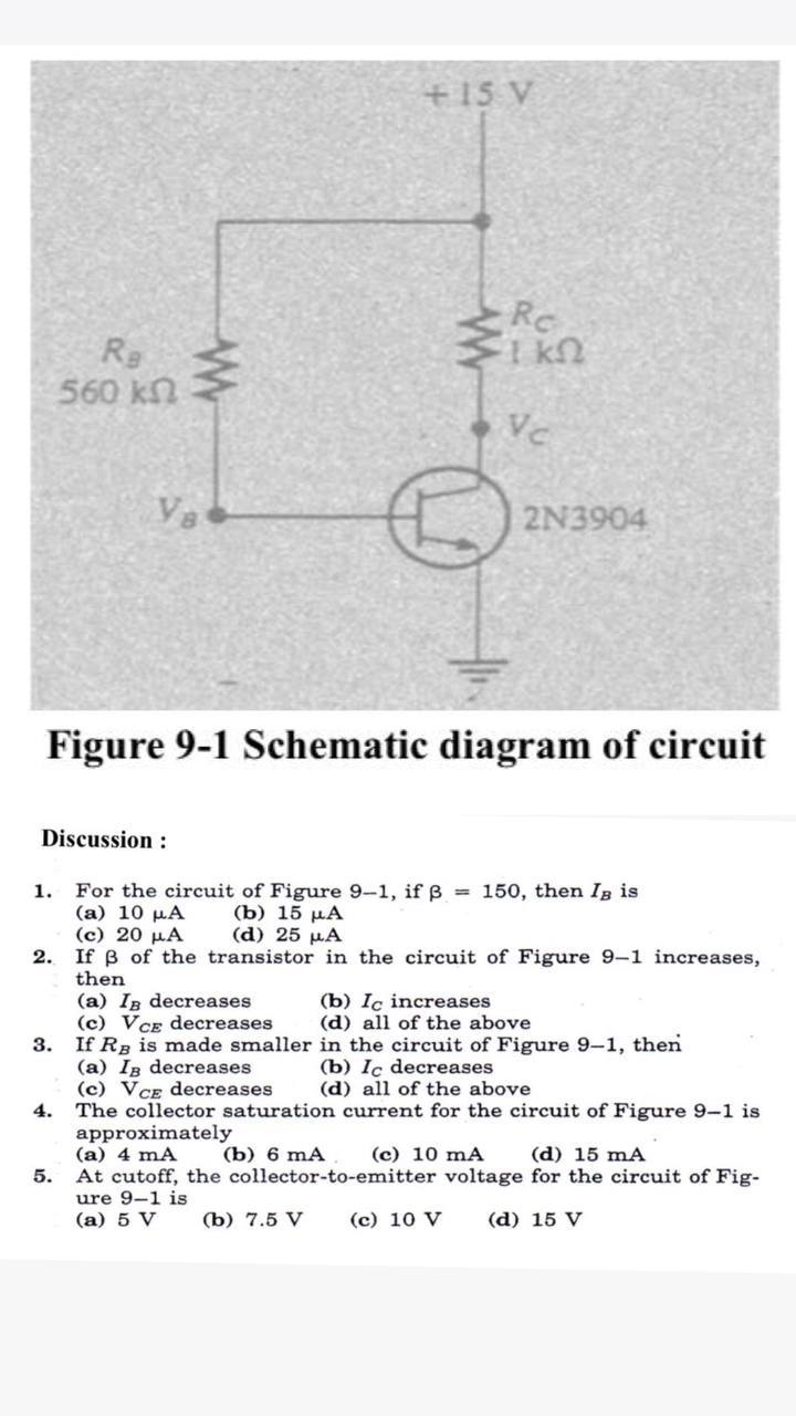

Transcribed Image Text:+15 V
Rc
Re
560 kn
Vc
Va
2N3904
Figure 9-1 Schematic diagram of circuit
Discussion :
1. For the circuit of Figure 9-1, if = 150, then Ig is
(a) 10 µA
(c) 20 µA
2. If B of the transistor in the circuit of Figure 9-1 increases,
then
(b) 15 µA
(d) 25 µA
(a) In decreases
(c) VCE decreases
(b) Iç increases
(d) all of the above
3. If Rg is made smaller in the circuit of Figure 9-1, then
(a) Ig decreases
(c) VCE decreases
4. The collector saturation current for the circuit of Figure 9-1 is
approximately
(a) 4 mA
At cutoff, the collector-to-emitter voltage for the circuit of Fig-
ure 9-1 is
(a) 5 V
(b) Ic decreases
(d) all of the above
(b) 6 mA
(c) 10 mA
(d) 15 mA
5.
(b) 7.5 V
(c) 10 V
(d) 15 V
Expert Solution
This question has been solved!
Explore an expertly crafted, step-by-step solution for a thorough understanding of key concepts.

Step by stepSolved in 5 steps with 1 images

Knowledge Booster


Learn more about
Need a deep-dive on the concept behind this application? Look no further. Learn more about this topic, electrical-engineering and related others by exploring similar questions and additional content below.Similar questions
- Set up a midpoint bias for a JFET with IDSS = 14 mA and VGS(off) = -10 V. Use a 24 V dc source as the supply voltage. Show the circuit and resistor values. Indicate the value of ID. Indicate the value of VGS. Indicate the value of VDS.arrow_forwardConsider the Zener diode circuit shown in Figure. The Zener Breakdown Voltage (Vz) is 5.6 V at Iz= 0.1mA. Zener resistance is r,= 10 0. What is Vo without load (RL= ∞) ? R= 0.5 kQ Vo Vps= 10 Varrow_forward1) AC power in a load can be controlled by using a. Two SCR's in parallel opposition b. Two SCR's in series c. Three SCR's in series d. Four SCR's in series 2) The advantage of using free - wheeling diode in half controlled bridge converter is that a. There is always a path for the ac current independent of the ac line b. There is always a path for the dc current independent of the ac line c. There is always a path for the dc current dependent of the ac line d. There is always a path for the ac current dependent of the ac line 3) Silicon controlled rectifier can be turned on a. By applying a gate pulse and turned off only when current becomes zero b. And turned off by applying gate pulse c. By applying a gate pulse and turned off by removing the gate pulse d. By making current non zero and turned off by making current zeroarrow_forward
- 3 A peak rectifier (peak tollower) Cir cuit is gian below. Vs is a GOH3 Sinuscidal Vollge with peak value Upz50V. 50V. The load resistance R= Sk . Find the Vallke of the capacitance C Such that the peak- to-peak ripple 2 volts. (idenl diede) Voltage Vr Vsarrow_forwardConsider the Zener diode circuit shown in Figure. The Zener Breakdown Voltage (Vz) is 5.6 V at Iz= 0.1mA. Zener resistance is rz= 10 0. What is Vo without load (RL= ) ? R= 0.5 ko Vo R Vps= 10 Varrow_forwardDraw the circuit diagram for a full-wave bridge rectifier with a resistance as the load.arrow_forward
- A 4.7 zener diode is connected to the base resistor. The left side of the resistor sits at about 12V. The right side of the biasing resistor is connected to the Zener and npn transistor. The Zener bias is 5mA. The base current needed is 80uA. What is the appropriate resistor for this circuit? (In kohms) Iarrow_forwardThe Figure 2 shows an electronic circuit designed for supplying power to a load (R1). The supply voltage 235V (RMS, AC) at frequency of 50HZ. The required DC voltage and power for the load are 24V and 3.6 W respectively. The Electrical Components of this AC to DC converter are: A full-wave rectifier to convert AC voltage to DC voltage. A regulator with transistor and Zener diode to ensure a constant voltage and power for the load. D1 Iide 91 Vaut VLoad D2 D3 Vde VI sine R1 RL Regulate Reetifier Figure 2. Complete Circuit Assume that the diodes are real diodes (NOT ideal diodes). The following information is available: The collector to base resistor of the regulator R1 = 5.0 k The transistor Q1 with B value of 24 is used for the regulator circuit. Determine the following quantities for this electronic device and fill the table below: Question Answer The voltage of Zener Diode (Vz) The current in R1 The DC current into the regulator | (Idc) Base current of transistor (IB) Collector…arrow_forwardVps = 10 V R = 0.1k02 ww -ovo R₁. Consider the Zener diode circuit shown in figure. The Zener diode voltage is Vz= 5.8V at Iz= 10mA and the Zener resistance is rz = 200. a) Find the output voltage for RL = 1k0 b) Find the change in the output voltage when the load resistance varies +ARL.arrow_forward
- Determine the peak output voltage for the bridge rectifier in this figure. Assuming the practical model, what PIV rating is required for the diode? The transformer is specified to have a 12 Vrms secondary voltage for the standard 110 V across the primary. * D3 Di 110 V Vpsec) D2 RL D 10 k . Vp(out)= 14.6 V, PIV= 14.3 V O vp(out)= 16.5 V, PIV= 13.6 V Vp(out)= 13.6 V, PIV= 13.3 V O vp(out)= 15.6 V, PIV= 16.3 V ell elllarrow_forwardanswer in 4 decimalsarrow_forwardI need some help with this problem. I need to create a power supply from 110v 60hz to regulated an output between 6 and 9 v. the image is the desire circuit to acomplish the possible solution. The resistor after the bridge rectifier will work as a surge protector or current limiter for the zener diode. the other is the Load resistor. I need some sort of calculations to prove the specific values for the components to operate according to the specs that I already explain. I know the capacitor will smooth the ripple voltage etc... but I need some guidance to get actual valuesarrow_forward
arrow_back_ios
SEE MORE QUESTIONS
arrow_forward_ios
Recommended textbooks for you
- Introductory Circuit Analysis (13th Edition)Electrical EngineeringISBN:9780133923605Author:Robert L. BoylestadPublisher:PEARSON
 Delmar's Standard Textbook Of ElectricityElectrical EngineeringISBN:9781337900348Author:Stephen L. HermanPublisher:Cengage Learning
 Programmable Logic ControllersElectrical EngineeringISBN:9780073373843Author:Frank D. PetruzellaPublisher:McGraw-Hill Education
  Fundamentals of Electric CircuitsElectrical EngineeringISBN:9780078028229Author:Charles K Alexander, Matthew SadikuPublisher:McGraw-Hill Education
 Electric Circuits. (11th Edition)Electrical EngineeringISBN:9780134746968Author:James W. Nilsson, Susan RiedelPublisher:PEARSON
 Engineering ElectromagneticsElectrical EngineeringISBN:9780078028151Author:Hayt, William H. (william Hart), Jr, BUCK, John A.Publisher:Mcgraw-hill Education,
Introductory Circuit Analysis (13th Edition)
Electrical Engineering
ISBN:9780133923605
Author:Robert L. Boylestad
Publisher:PEARSON
Delmar's Standard Textbook Of Electricity
Electrical Engineering
ISBN:9781337900348
Author:Stephen L. Herman
Publisher:Cengage Learning
Programmable Logic Controllers
Electrical Engineering
ISBN:9780073373843
Author:Frank D. Petruzella
Publisher:McGraw-Hill Education
Fundamentals of Electric Circuits
Electrical Engineering
ISBN:9780078028229
Author:Charles K Alexander, Matthew Sadiku
Publisher:McGraw-Hill Education
Electric Circuits. (11th Edition)
Electrical Engineering
ISBN:9780134746968
Author:James W. Nilsson, Susan Riedel
Publisher:PEARSON
Engineering Electromagnetics
Electrical Engineering
ISBN:9780078028151
Author:Hayt, William H. (william Hart), Jr, BUCK, John A.
Publisher:Mcgraw-hill Education,