Introductory Circuit Analysis (13th Edition)
13th Edition
ISBN: 9780133923605
Author: Robert L. Boylestad
Publisher: PEARSON
expand_more
expand_more
format_list_bulleted
Question
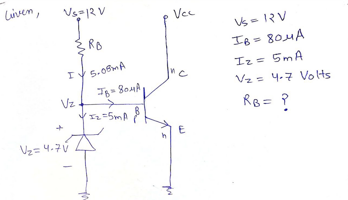
A 4.7 zener diode is connected to the base resistor. The left side of the resistor sits at about 12V. The right side of the biasing resistor is connected to the Zener and npn transistor. The Zener bias is 5mA. The base current needed is 80uA. What is the appropriate resistor for this circuit?
(In kohms) I
Expert Solution
arrow_forward
Step 1

Step by stepSolved in 2 steps with 2 images

Knowledge Booster
Similar questions
- A Full-wave bridge rectifier Circuit contains 4 Germanium diodes Cuse the Constant voltage drop model with VD = 0.30) driving ac a Load resistance of 10 kur. An Source with a Peak value of 4ou at bottz Vortage Source with a applied to the Circuit. a DIS 2 Determine the de value of the output wave form Determine the value of the Capacitor In uf needed to limit the output ripple vortage to 0.5 V if the Peak output voltage is equal to Upic -2VDarrow_forwardexplain how a pm signal is produced using a varactor diode in a phase modulator circuitarrow_forward1. A six-pulse uncontrolled recti load. The inductance is very 1 (a) Determine average load o (b) Determine the maximum (c) Determine the maximum (d) Determine average loac (e) Carefully sketch the wav diode conduction pattern.arrow_forward
- A silicon controlled rectifier (SCR) has a forward breakdown voltage of 230 V. When a gate current of 2 mA flows in the gate circuit. If a sinusoidal voltage of 400 V peak is applied, find the following: Firing angle. Average output voltage. Average current for a load resistance of 180 Ohms. Power outputarrow_forwardQuestion 4. Design a limiter circuit using only diodes and 10 K resistor to provide an output signal limited to +1.4 V.arrow_forward* When the peak output voltage is 100 V, the PIV for each diode in a center- tapped full-wave rectifier is (neglecting the diode drop) 200V O 100V 150V 55V If Vi is less than Vz. The Zener diode current is Zero Very low ********** High *< 0.5 Aarrow_forward
arrow_back_ios
arrow_forward_ios
Recommended textbooks for you
 Introductory Circuit Analysis (13th Edition)Electrical EngineeringISBN:9780133923605Author:Robert L. BoylestadPublisher:PEARSON
 Delmar's Standard Textbook Of ElectricityElectrical EngineeringISBN:9781337900348Author:Stephen L. HermanPublisher:Cengage Learning
 Programmable Logic ControllersElectrical EngineeringISBN:9780073373843Author:Frank D. PetruzellaPublisher:McGraw-Hill Education
 Fundamentals of Electric CircuitsElectrical EngineeringISBN:9780078028229Author:Charles K Alexander, Matthew SadikuPublisher:McGraw-Hill Education
 Electric Circuits. (11th Edition)Electrical EngineeringISBN:9780134746968Author:James W. Nilsson, Susan RiedelPublisher:PEARSON
 Engineering ElectromagneticsElectrical EngineeringISBN:9780078028151Author:Hayt, William H. (william Hart), Jr, BUCK, John A.Publisher:Mcgraw-hill Education,

Introductory Circuit Analysis (13th Edition)
Electrical Engineering
ISBN:9780133923605
Author:Robert L. Boylestad
Publisher:PEARSON

Delmar's Standard Textbook Of Electricity
Electrical Engineering
ISBN:9781337900348
Author:Stephen L. Herman
Publisher:Cengage Learning

Programmable Logic Controllers
Electrical Engineering
ISBN:9780073373843
Author:Frank D. Petruzella
Publisher:McGraw-Hill Education

Fundamentals of Electric Circuits
Electrical Engineering
ISBN:9780078028229
Author:Charles K Alexander, Matthew Sadiku
Publisher:McGraw-Hill Education

Electric Circuits. (11th Edition)
Electrical Engineering
ISBN:9780134746968
Author:James W. Nilsson, Susan Riedel
Publisher:PEARSON

Engineering Electromagnetics
Electrical Engineering
ISBN:9780078028151
Author:Hayt, William H. (william Hart), Jr, BUCK, John A.
Publisher:Mcgraw-hill Education,